
E3060 Sun roof
- Make
- Alfa Romeo
- Model
- 156 Factory Service Manual
- Year
- 1997–2002
- Section
- Electrical activation devices › E3060 Sun roof
E3060 Sun roof
Description
The sunroof offers extra ventilation for the interior compartment and ensures a rapid air exchange, if required, thus increasing passenger comfort.
The moving part of the roof consists of a glass panel and an internal sliding blind which enters the actual roof lining. The latter can also be operated manually and guarantees protection against the sun's rays.
The system is operated by a switch, located near the front courtesy light, which controls a motor with two different operating modes: press one end of the switch to raise the roof in "compass" fashion, and press the other end of the switch to slide the roof open and so pull the blind: when the switch is released, the roof stops in the position it is in at that moment. when the roof is closed, the blind is carried along a short distance by the forward motion of the panel.
The entire system consists of a single unit which comprises:
- the control unit A, which manages the operation of the roof;
- the actuating motor C;
- the control switch B;
- the end-of-travel switches D, located on a ring nut outside the motor, which stop the motor when the roof is fully open or closed.
For more details, see DESCRIPTION AND OPERATION: 7030 Sun roof and hood .
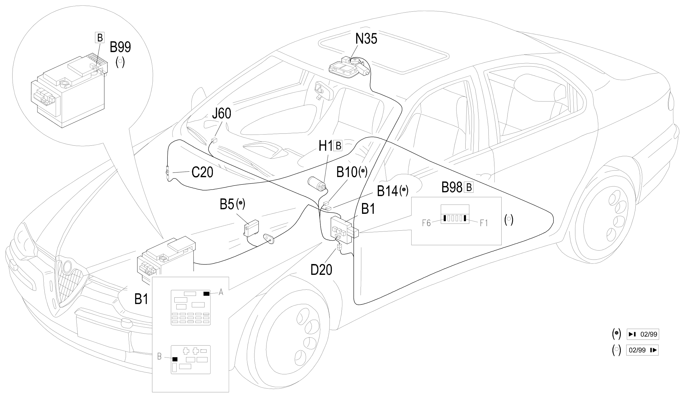
The sunroof circuit is protected by a specific fuse, and controlled by a relay which supplies other "ignition-operated" services. The fuse is located inside the junction unit, and the relay is located on the right hand side of the facia.
The sunroof can only be operated with the ignition on.
Description of operation
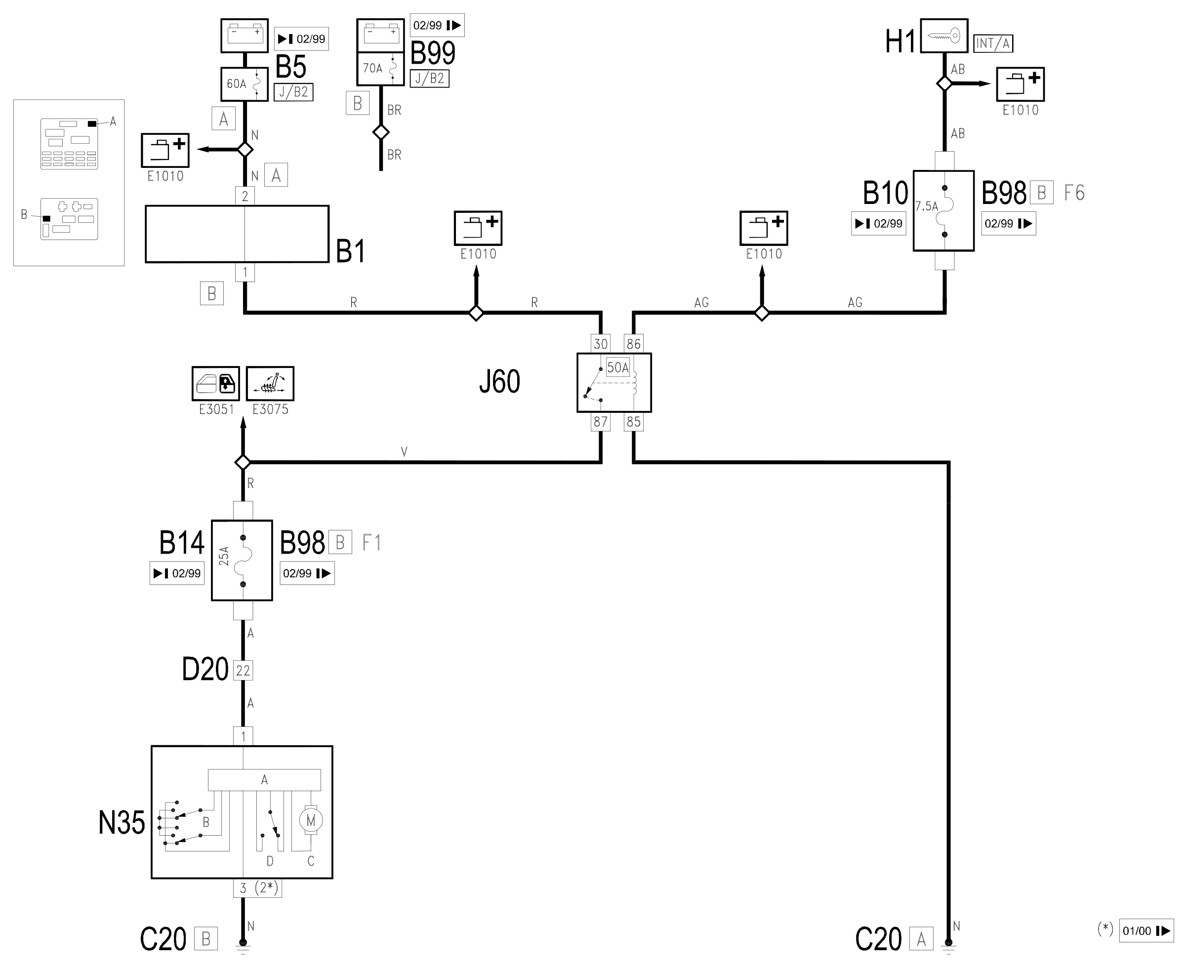
The optional services relay J60 controls the roof circuit (as well as the electric rear windows and heated seats: Wiring diagram E3051 REAR WINDOW MECHANISM and Wiring diagram E3075 HEATED SEATS ).
The coil of the relay J60 is energized when the ignition is switched on (INT/A) by the line for fuse B10 up to 2/99 or fuse F6 of the additional fuse box B98B from 2/99, while the supply at the relay contact arrives from the battery, through the line for maxifuse J/B2 (of B5 up to 2/99 or B99 from 2/99).
This supply passes through the sunroof B14 up to 2/99 or F1 of B98B from 2/99., which protects the circuit, and reaches the sunroof motor N35, at pin 1: it is actually a single unit which includes: the control unit A, the switch B, the motor itself C and the limit switches D.
The unit is also connected to earth C20 at pin 3.
The switch is therefore active when the ignition is on (INT/A). The control unit controls engine movement according to switch position.
Wiring diagram
Components
| Code | Component | See |
|---|---|---|
| B01 | Junction unit | description 5505A |
| B05 | MAXI FUSE-1 box | |
| B10 | Key-dependent supply fuse (INT/A) | |
| B14 | Sun-roof fuse | |
| B98 | Supplementary fuse box | description 5505A |
| B99 | Maxifuse box on battery | |
| C20 | Passenger side dashboard earth | description 5505A |
| D20 | Dashboard/rear connection | |
| H01 | Ignition switch | description 5520A |
| J60 | Optional services relay | |
| N35 | Sun roof motor | description 7030B |
Component location
Parts & tools for this job Staging For 1997 Alfa Romeo 156
- TOOLDigital multimeterSearch: automotive digital multimeter
- PARTAssorted fuse kitSearch: car fuse assortment kit
- TOOLWire crimper and connector kitSearch: wire crimper connector kit
Links open Amazon search results in a new tab. As an Amazon Associate I earn from qualifying purchases.