
E3075 Heated seats
- Make
- Alfa Romeo
- Model
- 156 Factory Service Manual
- Year
- 1997–2002
- Section
- Electrical activation devices › E3075 Heated seats
E3075 Heated seats
Description
The front seats may be optionally fitted with a special heating system (consisting of two heater elements located in the cushion and squab): these heat the seat to ease the discomfort of entering a cold passenger compartment in very cold weather, e.g. when the car is left outside for long periods during winter.
The heating device located on each seat consists of two resistors operated by a switch located on the side of the seat.
Once a certain temperature is reached, the heating action is automatically cut off by a thermal contact inside the device. An LED indicates when the heater is on.
The seat heating circuit is protected by a special fuse and is controlled by a relay which supplies other services controlled by the ignition. both are located on the right hand side under the facia.
The seat heating operates only whe the key is turned to MAR.
Description of operation
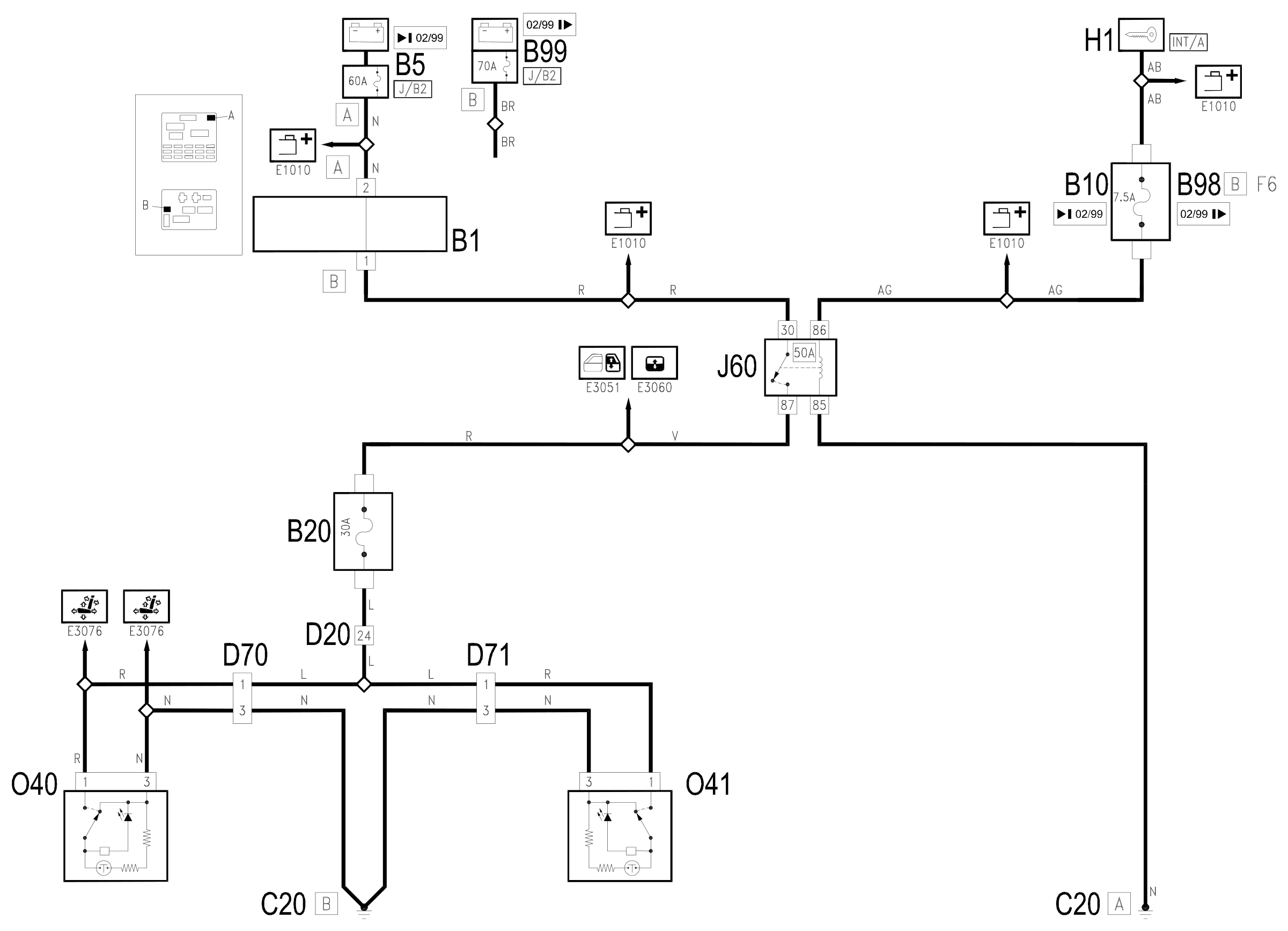
The optional services relay J60 controls the heating circuit for the seats as well as the electric rear windows and sun roof: Wiring diagram E3060 SUN ROOF , Wiring diagram E3051 REAR WINDOW MECHANISM .
r
The coil for relay J60 is energized when the ignition is switched on (INT/A) by the line for fuse B10, whilst the supply at the relay contact arrives from the battery, through the line for maxifuse J/B2 of B5.
s
The coil of the relay J60 is energized when the ignition is switched on (INT/A) by the line for fuse F6 of the additional fuse box B98B, while the supply at the relay contact arrives from the battery, through the line for maxifuse J/B2 of B99.
By pressing the switch on the seat the resistors for the heaters in the left and right seats, 040 and 041, connected in parallel, are supplied, until a thermal contact inside the heaters disconnects the resistors when the temperature exceeds a certain limit.
This supply passes through the heated seats fuse B20, which guarantees the protection of the circuit and reaches the switches in the seats through connection D70 (left seat) and D71 (right seat): the supply for the two devices is therefore controlled by the ignition (INT/A) and they are connected to earth C20.
When the resistors are on, an LED signals the operation of the device.
Wiring diagram
Components
| Code | Component | See |
|---|---|---|
| B01 | Junction unit | description 5505A |
| B05 | MAXI FUSE-1 box | |
| B10 | Key-dependent supply fuse (INT/A) | |
| B20 | Seat heating fuse | |
| B98 | Supplementary fuse box | description 5505A |
| B99 | Maxifuse box on battery | |
| C20 | Passenger side dashboard earth | description 5505A |
| D20 | Dashboard/rear connection | |
| D70 | Left seat connection | |
| D71 | Right seat connection | |
| H01 | Ignition switch | description 5520A |
| J60 | Optional services relay | |
| O40 | Left seat heater | |
| O41 | Right seat heater |
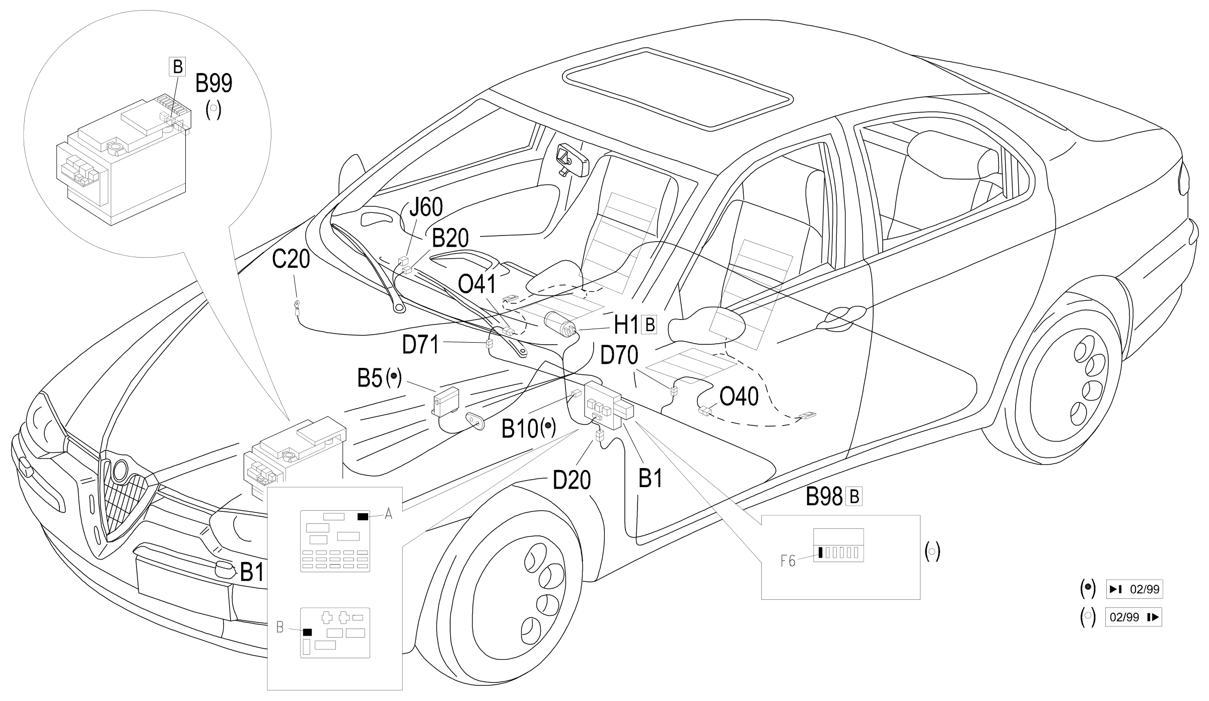
Component location
Parts & tools for this job Staging For 1997 Alfa Romeo 156
- TOOLDigital multimeterSearch: automotive digital multimeter
- PARTAssorted fuse kitSearch: car fuse assortment kit
- TOOLWire crimper and connector kitSearch: wire crimper connector kit
Links open Amazon search results in a new tab. As an Amazon Associate I earn from qualifying purchases.