
E3040 Door locking device (Euro3)
- Make
- Alfa Romeo
- Model
- 156 Factory Service Manual
- Year
- 1997–2002
- Section
- Electrical activation devices › E3040 Door locking device (Euro3)
E3040 Door locking device (Euro3)
Description
The lock motors of all four doors are activated simultaneously upon a command:
- from the key
- from the front door switches (knobs);
- from the remote control
Lock operation is controlled by the integrated service control unit located on the right hand side beneath the facia.
The control unit monitors lock status by means of signals received from switches located on the four locks (these signals are also used to time the lighting). A lock command is issued only when all doors are properly closed and the front locks are released. Conversely, a release command is issued only when the front catches are locked.
The control unit also runs a series of safety checks:
- switch position is checked at the end of each operation. If this position does not agree with the action carried out (e.g. if a door is open), a repulsion command is issued, i.e. the opposite manoeuvre is carried out to realign all the locks.
- if the control unit detects too many complete, consecutive lock/release manoeuvres - at least 8 within 20 seconds - the system cuts in to limit the manoeuvres: the system is inhibited in release position for 30 seconds.
- If battery voltage drops below 9 V during a lock/release operation, the system suspends the operation. If battery voltage is lower than 9 V at the outset, no command is issued.
The door lock circuit is protected by a special fuse located in the junction unit.
The remote control receiver has supplies (direct and controlled by the ignition) protected by two fuses located in the junction unit.
Description of operation
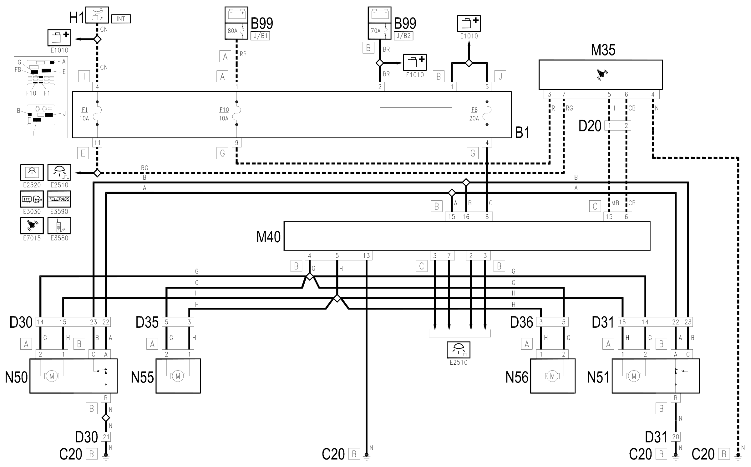
The integrated services control unit M40 which manages the operation of the central locking.
The direct supply for the control unit M40 (pin 8 of connector B) arrives directly from the battery via the line protect by maxifuse J/B2 (of B99) and fuse F8 of the junction unit B1.; pin 13 of connector B provides the reference earth.
The receiver of the remote control M35 receives a supply controlled by the ignition (INT) from the line for fuse F1 of the junction unit B1 and directly from the battery via the line of the maxifuse J/B1 (of B99) and fuse F10 of the junction unit B1.
The control unit M40 receives the following inputs:
- commands coming from the front locks N50 and N51 for locking (pin 15 of connector B) or for unlocking (pin 16 of connector B) the doors;
- signals on the state of the door locks, coming from the four geared motors N50, N51, N55 and N56, respectively at pins 2 and 3 of connector B and 3 and 7 of connector C. Wiring diagram E2510 ROOF LAMP .
- (only with remote control) the signals from the remote control M35 receiver for locking (pin 6 of connector C) or for unlocking (pin 15 of connector C);
In accordance with the strategy described above, the control unit M40 controls the locks: the signals for the motors of the front doors (N50 and N51) and rear doors (N55 ed N56) come from pins 4 and 5 of connector B.
Wiring diagram
Components
| Code | Component | See |
|---|---|---|
| B01 | Junction unit | description 5505A |
| B05 | MAXI FUSE-1 box | |
| B99 | Maxifuse box on battery | |
| C20 | Passenger side dashboard earth | description 5505A |
| D20 | Dashboard/rear connection | |
| D30 | Rear / front door connection left | |
| D31 | Right front door rear coupling/. | |
| D35 | Rear/right door connection left | |
| D36 | Rear/right door connection door | |
| H01 | Ignition switch | description 5520A |
| M35 | Alarm remote control receiver | description 5580E |
| M40 | Integrated services control unit | description 5505A |
| N50 | Right front door lock left | description 7005N |
| N51 | Right front door lock motor | description 7005N |
| N55 | Rear door lock geared motor left | description 7010N |
| N56 | Rear door lock geared motor right | description 7010N |
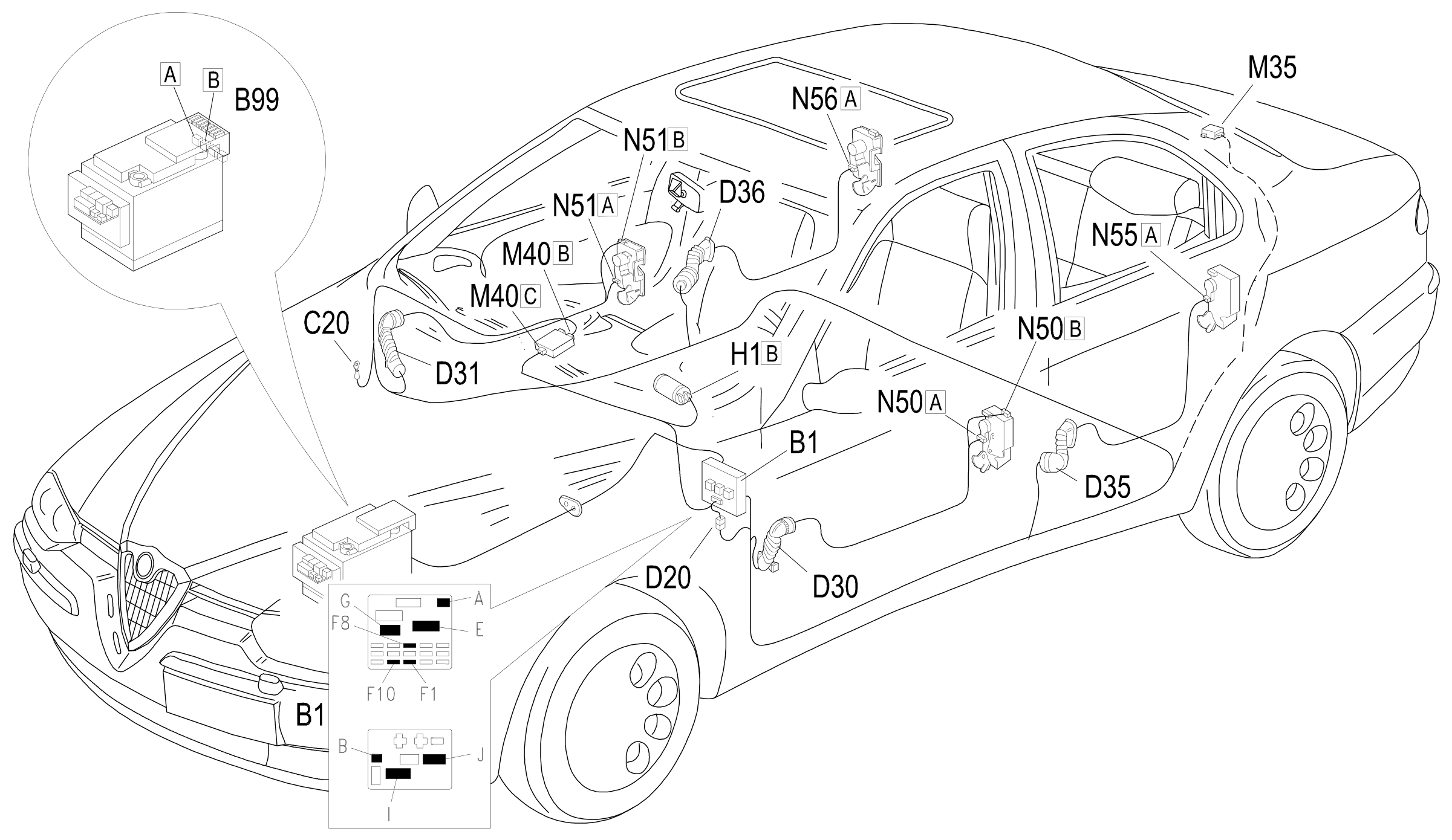
Component location
Parts & tools for this job Staging For 1997 Alfa Romeo 156
- TOOLTrim removal tool kitSearch: trim removal tool kit
- PARTTouch-up paintSearch: Alfa Romeo touch up paint
- PARTPanel clip assortmentSearch: Alfa Romeo panel clips assortment
Links open Amazon search results in a new tab. As an Amazon Associate I earn from qualifying purchases.