
E4080 Trip computer
- Make
- Alfa Romeo
- Model
- 147 Factory Service Manual
- Year
- 2000–2002
- Section
- Instruments › E4080 Trip computer
E4080 Trip computer
Description
The Trip Computer is only on the 'HIGH' instrument panel; it allows the following information to be displayed on the active matrix LCD:
- Instantaneous consumption [km/l]
- Average consumption [km/l]
- Range [km]
- Average speed [km/h]
- km travelled [km]
- Driving duration [hh:mm]
- Journey time [hh:mm]*
- km travelled [km]*
- Average speed [km/h]*
The values (*) are calculated from the last resest (pressing the SET button on the stalk unit right lever) or automatically after a stop of 2 h with the ignition off.
If an integrated radio-telephone-navigator is adopted, all the TRIP information is also displayed on the radio-telephone-navigator display.
For more details Characteristic of working principle 5560 Instruments .
The Trip Computer data are calculated within the instrument panel.
The instrument panel is a node on the CAN network through which it exchanges information with the Body Computer and the other electronic units. Wiring diagram E4010 INSTRUMENT PANEL
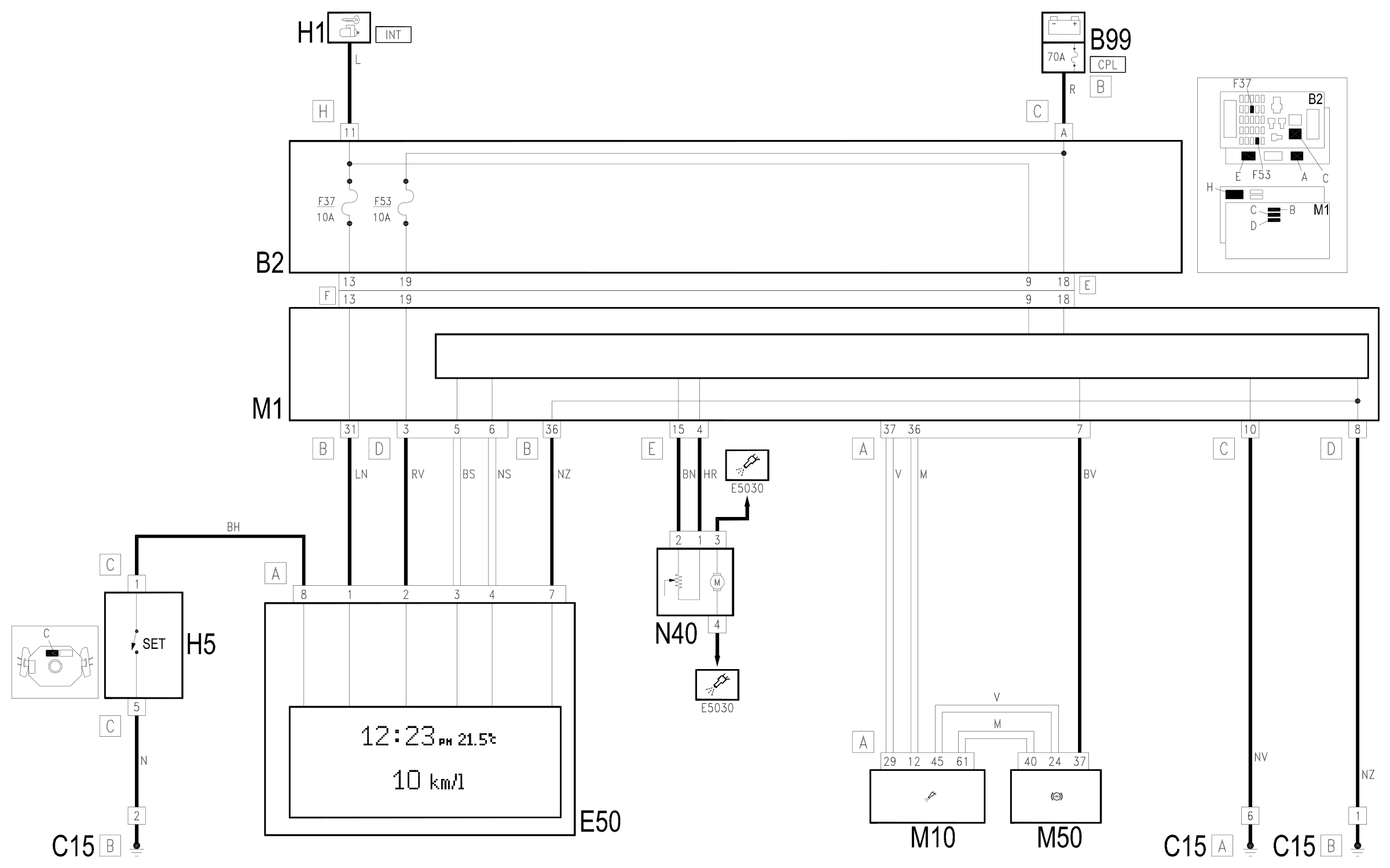
This diagram shows the operation of those functions relating to the instrument panel which also affect the Trip Computer.
Description of operation
The ignition-operated power supply (INT) of the instrument panel E50 reaches pin 1 of connector A through the line of fuse F37 of the unit under the dashboard B2; the direct supply reaches pin 2 of connector A through the line of fuse F53 of the unit under the dashboard B2; pin 7 of connector A is earthed (earth controlled by the Body Computer M1).
The instrument panel E50 is connected from pins 3 and 4 of connector A to the Body Computer M1 and via the latter to the whole CAN network: via CAN the signal for the electronic speedometer arrives (coming from the ABS control unit M50): this signal is replicated from pin 37 of M50 to pin 17 of connector A of the Body Computer M1.
The electronic rev counter receives the rpm signal coming via CAN from the engine management control unit M10.
The fuel gauge is controlled in accordance with the signals coming from the fuel gauge sender unit located in the fuel pump assembly N40 - at pins 4 and 15 of the Body Computer M1, and from here via CAN to the instrument panel E50.
The Trip Computer 'SET' button, located on the stalk unit H5, sends an earth signal to pin 8 of connector A of E50.
Wiring diagram
Components
| Code | Component | See |
|---|---|---|
| B02 | Junction unit under dashboard | description 5505A |
| B99 | Maxifuse box on battery | description 5530B |
| C15 | Facia earth, driver's side | |
| E50 | Instrument panel | description 5560B |
| H01 | Ignition switch | description 5520A |
| M01 | Body computer | description 5505A |
| M10 | Engine management ECU | description 1056B |
| M50 | ABS control unit | description 3340A |
| N40 | Fuel pump and sender unit | description 1040A |
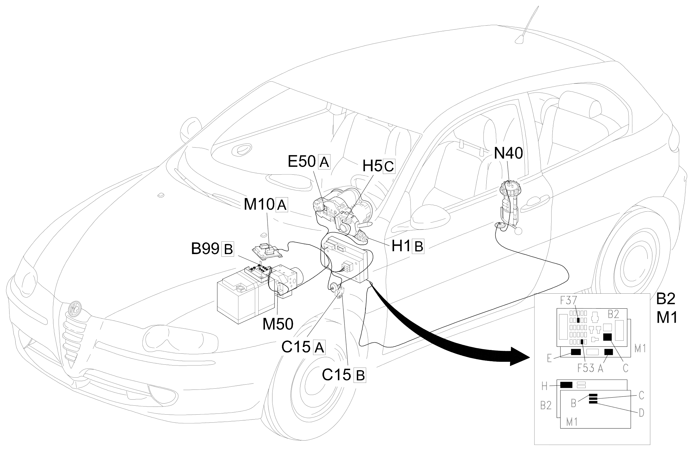
Component location
Parts & tools for this job Staging For 2000 Alfa Romeo 147
- TOOLDigital multimeterSearch: automotive digital multimeter
- PARTAssorted fuse kitSearch: car fuse assortment kit
- TOOLWire crimper and connector kitSearch: wire crimper connector kit
Links open Amazon search results in a new tab. As an Amazon Associate I earn from qualifying purchases.