
Introduction - ENGINE LUBRICATION SYSTEM
- Make
- Lancia
- Model
- Ypsilon Factory Service Manual
- Year
- 2003–2011
- Section
- Engine lubrication system › Introduction - ENGINE LUBRICATION SYSTEM
Introduction - ENGINE LUBRICATION SYSTEM
VIEW OF ASSEMBLY
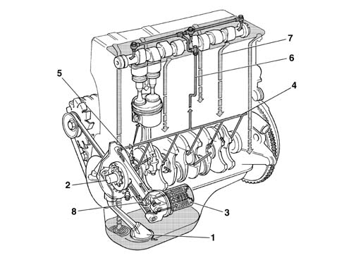
1, Suction pipe with filter mesh
2, Oil pump
3, Oil filter cartridge
4, Main longitudinal duct
5, Sprays (piston skirt cooling)
6, Vertical duct (camshaft support lubrication)
7, Oil return to the sump
8, Switch for engine oil pressure warning light
VIEW OF ASSEMBLY
The engine lubrication circuit is illustrated in the diagram.
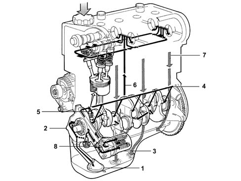
1, Suction pipe with filter mesh
2, Oil pump
3, Oil filter cartridge
4, Main longitudinal duct
5, Sprays (piston skirt cooling)
6, Vertical duct (camshaft support lubrication)
7, Oil return to the sump
8, Switch for engine oil pressure warning light
VIEW OF ASSEMBLY
The engine lubrication circuit is illustrated in the diagram.
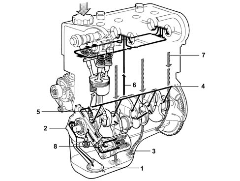
1, Suction pipe with filter mesh
2, Oil pump
3, Oil filter cartridge
4, Main longitudinal duct
5, Sprays (piston skirt cooling)
6, Vertical duct (camshaft support lubrication)
7, Oil return to the sump
8, Switch for engine oil pressure warning light
STRUCTURE
The engine lubrication system is represented below.
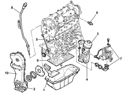
1 - Suction pipe with filter mesh
2 - Oil pump
3 - Oil filter cartridge
4 - Heat exchange (water oil) for cooling engine oi
5 - Spray jet (timing chain lubrication)
6 - Engine oil pressure warning light switch
7 - Turbocharger lubrication pipes
8 - Engine oil level dipstick
9 - Engine oil level maintenance and scraper wall
10 - Timing chain cover
Engine oil pump
The engine oil is drawn in from the sump by means of the vacuum created by the rotation of the sprockets fitted on the crankshaft.
Vacuum is present between the sprocket separating wall (2) and the oil sump suction pipe.
Pressure instead develops after the separating wall (2) in all the oil delivery pipes (4).
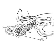
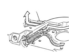
When the pressure exceeds 5 bar, the force exerted on the limiting valve (5) overcomes the reaction of the spring below and moves the valve to open the connecting pipe between the pressure chamber (3) and the low pressure chamber (1).
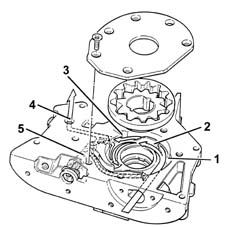
1, Low pressure chamber
2, Separating wall
3, Pressure chamber
4, Oil delivery pipe
5, Pressure limiting valve
ENGINE OIL PUMP
The engine oil is drawn in from the sump by means of the vacuum created by the rotation of the sprockets fitted on the crankshaft.
Vacuum is present between the sprocket separating wall (2) and the oil sump suction pipe.
Pressure instead develops after the separating wall (2) in all the oil delivery pipes (4).
When the pressure exceeds 5 bar, the force exerted on the limiting valve (5) overcomes the reaction of the spring below and moves the valve to open the connecting pipe between the pressure chamber (3) and the low pressure chamber (1).
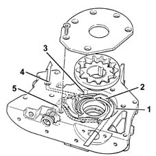
1, Low pressure chamber
2, Separating wall
3, Pressure chamber
4, Oil delivery pipe
5, Pressure limiting valve
ENGINE OIL PUMP
The engine oil is drawn in from the sump by means of the vacuum created by the rotation of the sprockets fitted on the crankshaft.
Vacuum is present between the sprocket separating wall (2) and the oil sump suction pipe.
Pressure instead develops after the separating wall (2) in all the oil delivery pipes (4).
When the pressure exceeds 5 bar, the force exerted on the limiting valve (5) overcomes the reaction of the spring below and moves the valve to open the connecting pipe between the pressure chamber (3) and the low pressure chamber (1).
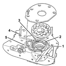
1, Low pressure chamber
2, Separating wall
3, Pressure chamber
4, Oil delivery pipe
5, Pressure limiting valve
Closed operating position of oil pressure limiting valve.
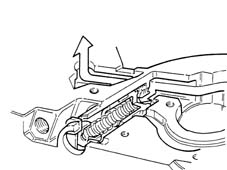
ENGINE OIL PUMP
OIL PRESSURE LIMITING VALVE IN CLOSED OPERATING POSITION
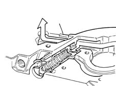
ENGINE OIL PUMP
OIL PRESSURE LIMITING VALVE IN CLOSED OPERATING POSITION
Bypass operating position of limiting valve.
ENGINE OIL PUMP
OIL PRESSURE LIMITING VALVE IN BYPASS OPERATING POSITION
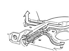
ENGINE OIL PUMP
OIL PRESSURE LIMITING VALVE IN BYPASS OPERATING POSITION
Parts & tools for this job Staging For 2003 Lancia Ypsilon
- PARTEngine gasket setSearch: Lancia Ypsilon 2003 engine gasket set
- TOOLTorque wrenchSearch: 3/8 inch torque wrench
- TOOLFeeler gauge setSearch: feeler gauge set
Links open Amazon search results in a new tab. As an Amazon Associate I earn from qualifying purchases.