
CAMSHAFTS in cylinder head - R.R. with head removed
- Make
- Lancia
- Model
- Thesis Factory Service Manual
- Year
- 2002–2009
- Section
- Timing system › CAMSHAFTS in cylinder head - R.R. with head removed
CAMSHAFTS in cylinder head - R.R. with head removed
Removing
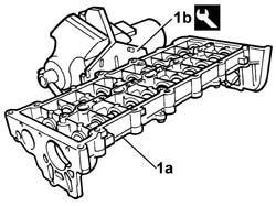
1. Position the camshaft housing (1a) in a vice using the tool (1b).
| Description | Code | Function | |
|---|---|---|---|
| 1b | Support | 1.860.470.001 | Service cylinder head |
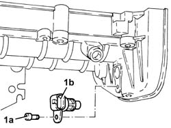
1. Undo the bolt (1a) and remove the cam angle sensor (1b).
- Check that the camshaft endfloat is within the recommended values using a dial gauge.
| Subject | Value | |
|---|---|---|
| Camshaft | mm | |
| End float |
- If the camshaft endfloat is not within the recommended values, replace the worn components when reassembling the cylinder head.
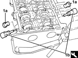
1. Remove the plugs (1a) and fit the camshaft timing tools (1b) on the camshaft housing.
Check that the tools are correctly fitted with the letters "A" and "S" in the housings in the inlet and exhaust camshafts.
| Description | Code | Function | |
|---|---|---|---|
| 1b | Templates | 1.870.896.900 | Engine tuning |
1. Undo the bolts fixing the camshaft gears.
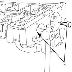
- Remove the camshaft timing tools from the camshaft housing.
| Description | Code | Function | |
|---|---|---|---|
| Templates | 1.870.896.900 | Engine tuning |
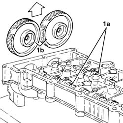
1. Release the camshafts (1a), as necessary and remove the camshaft gears (1b).
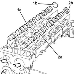
1. Extract the inlet side camshaft (1a) and plug (1b) using a suitable drift.
2. Extract the exhaust side camshaft (2a) and oil seal (2b) using a suitable drift.
- Remove the exhaust side camshaft oil seal.
Refitting
- Place the camshafts in their housings.
- Place the camshaft gears in their housings and secure them without tightening the bolts.
1. Fit the camshaft timing tools.
| Description | Code | Function | |
|---|---|---|---|
| 1 | Templates | 1.870.896.900 | Engine tuning |
Check that the tools are correctly fitted with the letters "A" and "S" in the housings in the inlet and exhaust camshafts.
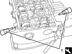
1. Tighten the bolts fixing the camshaft gears to torque.
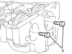
1. Fit the exhaust side camshaft front oil seal (1a) using the tool (1b).
| Description | Code | Function | |
|---|---|---|---|
| 1b | Fitting tool | 1.870.896.800 | Fitting exhaust camshaft oil seal |
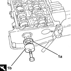
- Fit the inlet side camshaft plug.
- Place the exhaust side camshaft toothed drive pulley in its housing and secure it without tightening the bolt.
1. Place the cam angle sensor (1b) back in its housing and secure it tightening the bolt (1a) to torque.
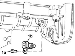
- Remove the camshaft housing complete with support tool from the vice and separate them.
| Description | Code | Function | |
|---|---|---|---|
| Support | 1.860.470.001 | Service cylinder head |
Removing
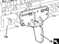
- Position the cylinder head (1a) in the vice using the tool (1b).
| Description | Code | Function | |
|---|---|---|---|
| 1b | Support | 1.860.470.000 | Cylinder head support |
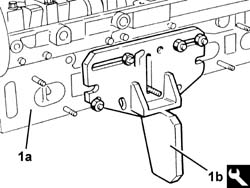
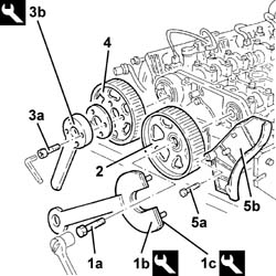
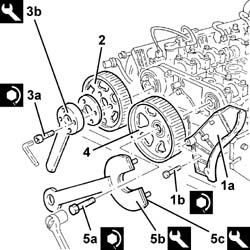
1. Undo the bolt (1a) for the exhaust side timing driven pulley using the tools (1b) and (1c) for counter-torque.
| Description | Code | Function | |
|---|---|---|---|
| 1b | Support for counter-torque | 1.860.831.000 | Loosen/tighten exhaust side camshaft drive pulley bolt |
| Description | Code | Function | |
|---|---|---|---|
| 1c | Support for counter-torque | 1.860.831.002 | Loosen/tighten bolt fixing exhaust side driven timing pulley |
2. Remove the exhaust side timing driven pulley.
3. Undo the inlet side timing driven pulley bolts (3a) using the tool (3b) for counter-torque.
| Description | Code | Function | |
|---|---|---|---|
| 3b | Counter-torque | 1.860.856.000 | Loosen/tighten inlet side camshaft drive pulley bolts |
4. Remove the inlet side timing driven pulley.
5. Undo the bolts (5a) and remove the side timing belt guards (5b).
1. Undo the bolts fixing the cam angle sensor to the camshaft front cap.
2. Undo the bolts (2a) and remove the camshaft caps (2b).
3. Remove the inlet side camshaft front supper upper half-bearing.
4. Remove the camshafts.
5. Remove the camshaft front oil seals.
6. Remove the inlet side camshaft front support lower half-bearing.
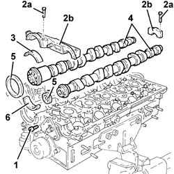
Refitting
- Place the inlet side camshaft front support lower half-bearing in its housing.
- Place the camshafts in their housings.
- Place the inlet side camshaft front support upper half-bearing in its housing.
1. - Place the camshaft caps (1a) in their housings and secure them tightening the bolts (1b) to the recommended torque.
| Value - daNm | Fastening | Component | Ø | |
|---|---|---|---|---|
| 1b | 1.4 - 2.0 (cylinder head side) | Bolt | CAMSHAFT CAPS | M7 |
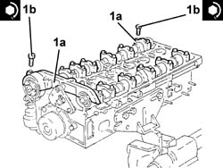
- Tighten the bolt fixing the cam angle sensor to the camshaft front cap.
| Value - daNm | Fastening | Component | Ø | |
|---|---|---|---|---|
| 0.9 - 1.2 | Bolt | CAM ANGLE SENSOR |
1. Fit the exhaust side camshaft front oil seal (1a) using the tool (1b).
| Description | Code | Function | |
|---|---|---|---|
| 1b | Fitting tool | 1.860.824.000 | Fitting exhaust camshaft front oil seal |
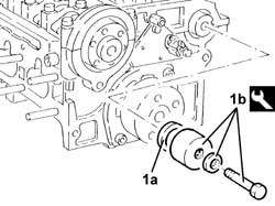
1. Fit the inlet side camshaft front oil seal (1a) using the tool (1b).
| Description | Code | Function | |
|---|---|---|---|
| 1b | Fitting tool | 1.860.844.000 | Fitting inlet camshaft front oil seal |
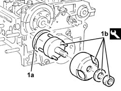
1. Place the timing belt side guards (1a) back in their housings and secure them using the bolts (1b).
| Value - daNm | Fastening | Component | Ø | |
|---|---|---|---|---|
| 1b | 0,9 - 1,2 | Bolts | TIMING BELT PROTECTIVE COVER(S) |
2. Place the inlet side timing driven pulley in its housing.
3. Tighten the bolts (3a) for the inlet side toothed timing driven pulley using the tool (3b) for counter-torque.
| Value - daNm | Fastening | Component | Ø | |
|---|---|---|---|---|
| 3a | (inlet camshaft side) 0.9 - 0 1.2 | Bolt | TIMING DUCT PULLEY | M6 |
| Description | Code | Function | |
|---|---|---|---|
| 3b | Counter-torque | 1.860.856.000 | Loosen/tighten inlet side camshaft drive pulley bolts |
4. Place the exhaust side timing driven pulley in its housing.
5. Tighten the bolt (5a) for the exhaust side toothed timing driven pulley using the tools (5b) and (5c) for counter-torque.
| Value - daNm | Fastening | Component | Ø | |
|---|---|---|---|---|
| 5a | (Exhaust camshaft side) 11.0 - 15.9 | Bolt | TIMING DUCT PULLEY | M12 |
| Description | Code | Function | |
|---|---|---|---|
| 5b | Support for counter-torque | 1.860.831.000 | Loosen/tighten exhaust side camshaft drive pulley bolt |
| Description | Code | Function | |
|---|---|---|---|
| 5c | Countertorque | 1.860.848.000 | Engine flywheel lock |
- Remove the cylinder head from the vice and place it in the housing on the support tool.
| Description | Code | Function | |
|---|---|---|---|
| Support | 1.860.470.000 | Cylinder head support |
Removing
- Position the cylinder head (1a) in the vice using the tool (1b).
| Description | Code | Function | |
|---|---|---|---|
| 1b | Support | 1.860.470.000 | Cylinder head support |
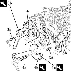
1. Undo the bolt (1a) for the exhaust side timing driven pulley using the tools (1b) and (1c) for counter-torque.
| Description | Code | Function | |
|---|---|---|---|
| 1b | Support for counter-torque | 1.860.831.000 | Loosen/tighten bolt fixing exhaust side driven timing pulley |
| Description | Code | Function | |
|---|---|---|---|
| 1c | Support for counter-torque | 1.860.831.002 | Loosen/tighten bolt fixing exhaust side driven timing pulley |
2. Remove the exhaust side timing driven pulley.
3. Undo the inlet side timing driven pulley bolts (3a) using the tool (3b) for counter-torque.
| Description | Code | Function | |
|---|---|---|---|
| 3b | Counter-torque | 1.860.856.000 | Loosen/tighten bolts fixing inlet side toothed driven timing pulley |
4. Remove the inlet side timing driven pulley.
5. Undo the bolts (5a) and remove the side timing belt guards (5b).
1. Undo the bolts fixing the cam angle sensor to the camshaft front cap.
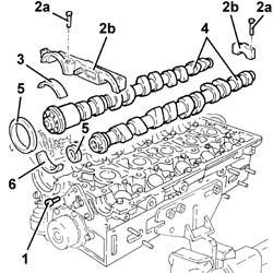
2. Undo the bolts (2a) and remove the camshaft caps (2b).
3. Remove the inlet side camshaft front supper upper half-bearing.
4. Remove the camshafts.
5. Remove the camshaft front oil seals.
6. Remove the inlet side camshaft front support lower half-bearing.
Refitting
- Place the inlet side camshaft front support lower half-bearing in its housing.
- Place the camshafts in their housings.
- Place the inlet side camshaft front support upper half-bearing in its housing.
1. - Place the camshaft caps (1a) in their housings and secure them tightening the bolts (1b) to the recommended torque.
| Value - daNm | Fastening | Component | Ø | |
|---|---|---|---|---|
| 1b | 1.4 - 2.0 (cylinder head side) | Bolt | CAMSHAFT CAPS | M7 |
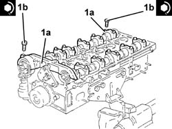
- Tighten the bolt fixing the cam angle sensor to the camshaft front cap.
| Value - daNm | Fastening | Component | Ø | |
|---|---|---|---|---|
| 0.9 - 1.2 | Bolt | CAM ANGLE SENSOR |
1. Fit the exhaust side camshaft front oil seal (1a) using the tool (1b).
| Description | Code | Function | |
|---|---|---|---|
| 1b | Fitting tool | 1.860.824.000 | Fitting exhaust camshaft front oil seal |
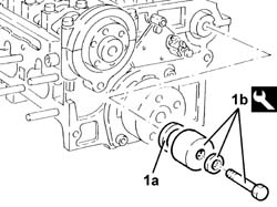
1. Fit the inlet side camshaft front oil seal (1a) using the tool (1b).
| Description | Code | Function | |
|---|---|---|---|
| 1b | Fitting tool | 1.860.844.000 | Fitting inlet camshaft front oil seal |
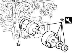
1. Place the timing belt side guards (1a) back in their housings and secure them using the bolts (1b).
| Value - daNm | Fastening | Component | Ø | |
|---|---|---|---|---|
| 1b | 0,9 - 1,2 | Bolts | TIMING BELT PROTECTIVE COVER(S) |
2. Place the inlet side timing driven pulley in its housing.
3. Tighten the bolts (3a) for the inlet side toothed timing driven pulley using the tool (3b) for counter-torque.
| Value - daNm | Fastening | Component | Ø | |
|---|---|---|---|---|
| 3a | (inlet camshaft side) 0.9 - 0 1.2 | Bolt | TIMING DUCT PULLEY | M6 |
| Description | Code | Function | |
|---|---|---|---|
| 3b | Counter-torque | 1.860.856.000 | Loosen/tighten inlet side camshaft drive pulley |
4. Place the exhaust side timing driven pulley in its housing.
5. Tighten the bolt (5a) for the exhaust side toothed timing driven pulley using the tools (5b) and (5c) for counter-torque.
| Value - daNm | Fastening | Component | Ø | |
|---|---|---|---|---|
| 5a | (Exhaust camshaft side) 11.0 - 15.9 | Bolt | TIMING DUCT PULLEY | M12 |
| Description | Code | Function | |
|---|---|---|---|
| 5b | Support for counter-torque | 1.860.831.000 | Loosen/tighten bolt fixing exhaust side driven timing pulley |
| Description | Code | Function | |
|---|---|---|---|
| 5c | Counter-torque | 1.860.848.000 | Loosen/tighten bolt fixing exhaust side driven timing pulley |
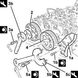
- Remove the cylinder head from the vice and place it in the housing on the support tool.
| Description | Code | Function | |
|---|---|---|---|
| Support | 1.860.470.000 | Service cylinder head |
Parts & tools for this job Staging For 2002 Lancia Thesis
- PARTEngine gasket setSearch: Lancia Thesis 2002 engine gasket set
- TOOLTorque wrenchSearch: 3/8 inch torque wrench
- TOOLFeeler gauge setSearch: feeler gauge set
Links open Amazon search results in a new tab. As an Amazon Associate I earn from qualifying purchases.