
Bosch eobd injection system
- Make
- Lancia
- Model
- Thesis Factory Service Manual
- Year
- 2002–2009
- Section
- Petrol fuel injection system › Bosch eobd injection system
BOSCH EOBD INJECTION SYSTEM
SPECIFICATIONS
Function
The Bosch Motronic system belongs the category of systems integrated with:
- inductive discharge, digital, electronic ignition
- static advance.
- sequential, phased type electronic injection (1 - 2 - 4 - 5 - 3).
The Engine Management Node controls:
- the idle air flow rate set through the electronic throttle;
- the moment of ignition with the advantage of maintaining smooth engine operation as the environmental parameters and loads applied vary.
The Engine Management Node controls and manages the injection so that the air/fuel ratio is always sufficiently close to the stoichiometric value in order to ensure optimum conversion efficiency for the catalyzer; in full power and high usage conditions the mixture is enriched to guarantee maximum performance.
The main functions of the system are basically as follows:
- self-learning;
- system self-adjustment;
- self-diagnosis;
- CODE recognition;
- cold starting check;
- combustion - Lambda sensor check;
- check on phase transformer and modular intake manifold
- detonation control;
- check on mixture enrichment during acceleration;
- fuel cut-off during release of accelerator pedal;
- fuel vapour recovery;
- control of maximum rpm;
- fuel supply - electric fuel pump control;
- connection with climate control system;
- recognition of cylinder position;
- injection time adjustment;
- ignition advance adjustment;
- idle speed control;
- control of engine cooling fan;
- connection with automatic transmission control unit (where fitted);
- connection with ABS control unit;
- connection with instrument panel.
- Fuel System fault diagnosis;
- catalyzer fault diagnosis;
- Lambda sensors fault diagnosis;
- Misfire fault diagnosis;
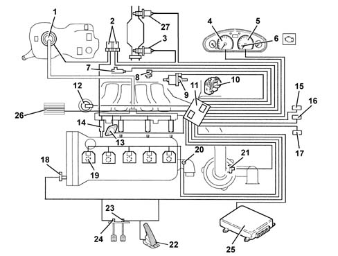
- 1 Fuel pump.
- 2 Relays.
- 3 Lambda sensor (upstream).
- 4 Speedometer.
- 5 Rev counter.
- 6 Injection warning light.
- 7 Knock sensors.
- 8 RPM sensor.
- 9 Fuel vapour recirculation solenoid.
- 10 Throttle body built into DVE
- 11 Engine Management Node.
- 12 Modular intake manifold solenoid.
- 13 Phase transformer.
- 14 Injectors.
- 15 Climate control system connector.
- 16 Tester connector.
- 17 CODE connector.
- 18 Timing sensor.
- 19 Ignition coils.
- 20 Coolant temperature sensor.
- 21 Air flow meter with air temperature sensor.
- 22 Accelerator pedal potetiometer.
- 23 Brake pedal switch.
- 24 Clutch pedal switch.
- 25 Automatic transmission control unit (where necessary).
- 26 Engine coolant temperature control unit.
- 27 Lambda sensor (downstream).
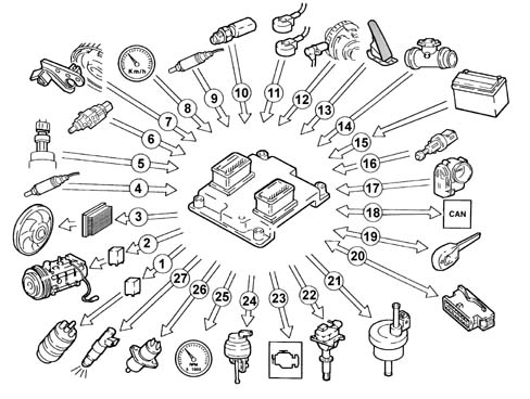
- 1 Fuel pump.
- 2 Air conditioning compressor.
- 3 Fan.
- 4 Lambda sensor downstream of the catalytic converter
- 5 Quadrinary.
- 6 Brake pedal switch.
- 7 Timing sensor.
- 8 Speedometer.
- 9 Lambda sensor upstream of the pre-catalyzer
- 10 Coolant temperature sensor.
- 11 Knock sensor (two).
- 12 RPM sensor.
- 13 Accelerator pedal potetiometer.
- 14 Air flow meter with air temperature sensor.
- 15 Battery.
- 16 Clutch pedal switch.
- 17 Throttle body built into DVE
- 18 CAN line (for communication with ABS/ASR control units).
- 19 Lancia CODE.
- 20 Diagnotic socket.
- 21 Fuel vapour recirculation solenoid.
- 22 Ignition coils.
- 23 Injection warning light.
- 24 Modular intake manifold solenoid.
- 25 Rev counter.
- 26 Phase transformer.
- 27 Injectors.
OPERATION
Operating strategies
General remarks
Injection system
The essential conditions that must always be satisfied in the preparation of the air/fuel mixture for the smooth operation of controlled ignition engines are, basically:
- the "metering" (air/fuel ratio) should be kept as close as possible to the stoichiometric value to ensure the maximum conversion capacity of the catalytic converters (max. efficiency).
- the "homogeneity" of the mixture comprising petrol diffused in the air as finely and evenly as possible.
The information that the Engine Management Node processes to ensure optimum metering is received by means of electrical signals sent by:
- *- air flow meter and air temperature sensor, for the exact intake air quantity.
- rpm sensor, which produces an alternating single phase signal whose frequency indicates the engine speed. This signal is used by the Engine Management Node for detecting misfire.
- throttle potentiometer for recognizing the acceleration conditions required.
- coolant temperature sensor located on the thermostat.
- Lambda sensors for determining the oxygen content of the exhaust gases and, through the downstream sensor, for diagnosing the efficiency of the catalyzers.
Ignition system.
The ignition system is the static advance, inductive discharge type (i.e. with no high tension distributor) with power modules inside the Engine Management Node.
In this ignition system each coil supplies the spark plugs for the relevant cylinder.
The advantages of this solution are:
- less electrical overload;
- guarantee of constant discharge at each spark plug.
There is a map stored in the Engine Management Node containing the entire series of optimum ignition advance values (for the cylinder in the explosion stroke) that the engine can adopt depending ont he engine speed and load requirements.
The Engine Management Node makes corrections to the advance value mainly depending on:
- engine coolant temperature.
- intake air temperature.
- detonation.
- throttle valve position.
The information that the Engine Management Node processes to operate the coils is received by means of electrical signals sent by:
- air flow meter with built in air temperature sensor, for the exact intake air quantity.
- rpm sensor, which produces an alternating single phase signal whose frequency indicates the engine speed.
- 2 detonation sensors (at the rear of the cylinder block one between the 1st and 2nd cylinders, the other between the 4th and 5th) to recognize the cylinder where detonation is taking place and correct the ignition advance.
- throttle position potentiometer to recognize minimum load, partial load and full gas conditions.
- timing sensor.
Self-learning.
The Engine Management Node implements the self-learning logic in the following conditions:
removing-refitting or replacing the Engine Management Node.
removing-refitting or replacing the throttle casing.
The values stored in the Engine Management Node memory are preserved when the battery is disconnected.
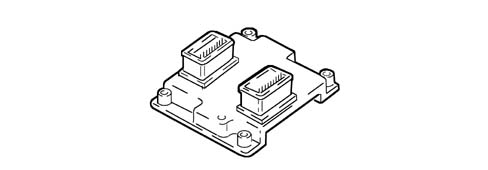
System self-adjustment.
The Engine Management Node is equipped with a self-adjustment function that is designed to recognize the changes that take place in the engine due to the processes of bedding in and ageing of both the components and the engine itself in time.
These changes are memorized in the form of modifications to the basic map and are designed to adapt the operation of the system to the gradual alterations in the engine and the components compared with when they were new.
This self-adjustment function also makes it possible to compensate for the inevitable differences in any replacement components (due to production tolerances).
From the analysis of the exhaust gases, the Engine Management Node modifies the basic map in relation to the engine specifications when new.
The self-adjustment parameters are not cancelled if the battery is disconnected.

Self-diagnosis
The Engine Management Node auto-diagnostic system checks that the system is working properly and signals any irregularities by means of an MIL warning light in the instrument panel with a standardized ideogram and colour laid down by European regulations. This warning lights signals both engine management faults and faults that are detected by the EOBD strategies.
The MIL warning light operating logic is as follows:
- with the ignition on, the warning light comes on and remains on until the engine has been started up. The Engine Management Node self-diagnostic system checks the signals coming from the sensors comparing them with the permitted limits:
Siganalling of faults during stating:
- the failure of the warning light to go out when the engine has been started indicates that there is an error memorized in the Engine Management Node.
Signalling of faults during operation:
- the warning light flashing indicates possible damage to the catalyzer through the presence of misfire.
- the warning light coming on constantly indicates the presence of engine management or EOBD errors.
RECOVERY.
From time to time the Engine Management Node defines the type of recovery according to the components that are faulty. The recovery parameters are managed by components that are not faulty.
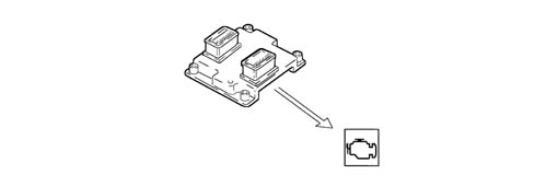
Code recognition.
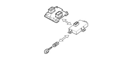
The moment the Body Computer receives the ignition ON signal, it converses with the Engine Management Node to allow starting. For vehicles equipped with Passive Entry see {DF55].
Cold starting check.
In cold starting conditions the following occurs:
- a natural weakening of the mixture which results in poor evaporation (poor turbulence of the fuel particles at low temperatures).
- reduced evaporation of the fuel.
- condensation of the fuel on the internal walls of the intake manifold.
- increased viscosity of the lubricant oil.
The Engine Management Node recognizes this condition and corrects the basic injection time:
- coolant temperature.
- intake air temperature.
- battery voltage.
- engine speed.
The ignition advance only depends on the number of revs and the temperature of the engine coolant.
Whilst the engine is warming up, the Engine Management Node operates the motorized throttle to regulate the quantity of air required to ensure that the engine does not cut out.
The rotation speed decreases proportionally as the engine temperature increases until the nominal value is reached when the engine has warmed up.
Combustion - Lambda sensor check.
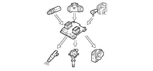
In EOBD systems the Lambda sensors, which are all the same type, are located upstream of the catalyzer and downstream of the catalyzer. The upstream sensor carries out the mixture strength control known as 1st closed loop. The sensor downstream of the catalyzer is used for the fault diagnosis of the catalyzer and to modulate the 1st loop parameters. With this in mind, the adaptation of the second loop is designed to recover both production differences and the slight changes in the response of upstream sensors that may occur due to ageing and pollution. This control is known as the 2nd closed loop.
Check on phase transformer and modular intake manifold.
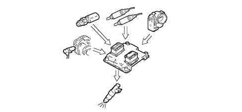
In order to ensure the optimum quantity of air drawn in by the engine, the Engine Management Node controls:
- the intake timing in two angular positions.
- the geometry of two different length intake manifolds.
The Engine Management Node sets the "open" stage at maximum speed:
- cam advance = 18° engine
- intake chamber long ducts.
In other engine operating conditions, the Engine Management Node selects the most suitable configuration for optimum performance, consumption and emissions.
In the release stage, the chamber intake ducts are always short.
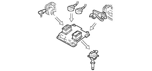
Knock control.
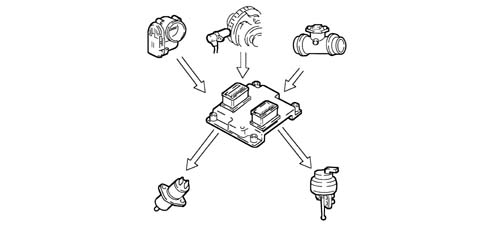
The Engine Management Node detects the presence of detonation (engine knock) by processing the signal from the relevant sensors.
The Engine Management Node continuously compares the signals coming from the sensors with a threshold which is, in turn, continually updated to take into account background noise and engine ageing.
The Engine Management Node is capable of detecting the presence of detonation (or the onset of detonation) in every cylinder and reducing the ignition advance for the cylinder concerned (in steps of 3° up to a maximum of 6°) until it disappears. Later on, the advance is gradually restored to the basic value (in steps of 0.8°).
In acceleration conditions a higher threshold is used to take into account the increased engine noise under these circumstances.
The detonation control logic is also equipped with a self-adaptation logic which memorizes the advance reductions that are continuously repeated in order to adapt the map to the different operating conditions that the engine finds itself in.
Check on enrichment during acceleration.
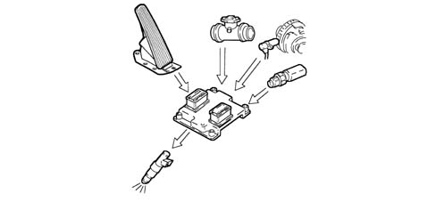
If, during an acceleration request, the variation in the air flow rate signal exceeds a predefined increase, the Engine Management Node increases the injection (time) to reach the number of revs required rapidly.
Recovery:
the Engine Management Node replaces the signal coming from the faulty air flow meter with the throttle potentiometer signal.
Fuel cut off during over-run (cut-off)
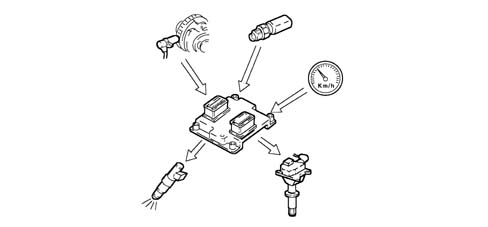
Whilst the accelerator pedal is released and beyond a preset engine rpm level, the Engine Management Node:
- cuts off the supply to the injectors.
- reactivates the supply to the injectors at 1300 ¸ 1500 rpm.
If there is no supply, the number of reves decreases at a speed dependent on the vehicle driving conditions.
Before the idle speed is reached, the progress of the rev decrease is checked.
If it is above a certain value, the fuel supply is partly restored so that there is a "gentle accompaniment" towards the idle speed.
The levels for restoring the supply and for the fuel cut off vary according to the:
- engine coolant temperature.
- speed of the vehicle.
- engine rpm.
Fuel vapour recovery.
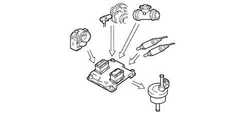
The remaining vapours are absorbed by a charcoal filter (canister) from where they can be drawn in and burnt by the engine during the appropriate stages.
This is managed by means of a solenoid valve which opens and closes the duct towards the intake chamber.
The Engine Management Node implements an adjustment strategy by controlling the value supplied by the Lambda sensor during the canister scrubbing stages:
- if there is excess oxygen in the composition of the exhaust gases (lean mixture), this means that there are no petrol vapours present in the canister and therefore the solenoid valve is closed after a short time;
- if the mixture is enriched, the Engine Management Node keeps the solenoid valve open, allowing the scrubbing of the filter and adjusting the injection time. The opening is maintained until the variation in the mixture is detected (lean condition) and then it is closed again. The filter scrubbing capacity is nominally limited to percentage points of the air flow meter reading so that there is a balance and the driveability of the vehicle is disturbed as little as possible.
Maximum rpm check.
Depending on the speed reached by the engine, the Engine Management Node:
- above 6800 rpm, cuts off the supply to the injectors (a maximum of 7200 rpm can be reached for not more than 3 secs.).
- below 6800 rpm, the operation of the injectors is restored.
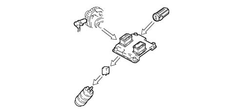
Fuel supply - electric fuel pump check
The Engine Management Node supplies the pump:
- with the ignition ON for 0.8 secs.
- with the ignition in AVV and the engine speed > 22.8 rpm
The Engine Management Node interrupts the supply to the pump:
- with the key in OFF position.
- with the engine speed < 22.8 rpm.
The returnless fuel supply system ensures a constant pressure of 3.5 bar.
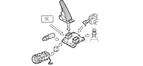
Connection with climate control system.
When there is a request for power due to the compressor having been switched on, the Engine Management Node operates the throttle to increase the air flow rate.
The Engine Management Node momentarily interrupts the supply to the compressor:
- during starting.
- switching it off beyond 6200 rpm.
- switching it off when the engine temperature is > 112°C.
- during take off with the accelerator fully depressed.
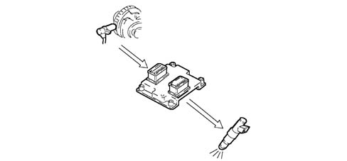
Recognition of cylinder position.
During each revolution of the engine the Engine Management Node recognizes which cylinder is in the explosion stroke and controls the ignition and the injection sequence at the appropriate cylinder.
If there is no timing sensor signal, the Engine Management Node:
- deactivates the detonation sensors.
- maintains the phased injection with the vehicle moving.
- the vehicle does not start with the timing sensor broken.
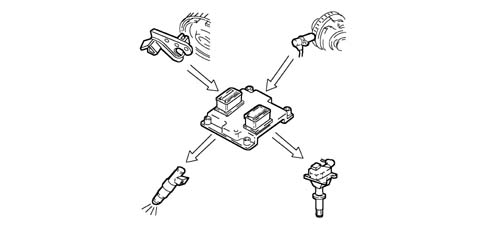
Injection time adjustment
The Engine Management Node calculates the injector opening time and controls them with extreme precision and speed depending on the:
- engine load (number of revs and air flow rate).
- battery voltage
- engine coolant temperature.
The injection is the phased, sequential type for each cylinder and takes place corresponding to the optimum injection point "start of injection", with the "end of injection" point remaining fixed.
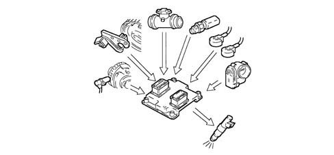
Ignition advance adjustment.
Thanks to a map stored in its memory, the Engine Management Node is capable of calculating the ignition advance depending on:
- the engine load (minimum, partial, full, according to the number of revs and the air flow rate).
- the intake air temperature.
- the engine coolant temperature.
The ignition can be selectively delayed at the cylinder required, recognized through the combination of values recorded by the rpm and timing sensors.
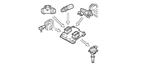
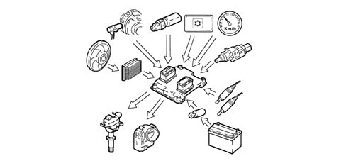
Idle speed check.
The Engine Management Node recognizes the minimum condition through the accelerator pedal being in the "released" position.
To control the idle speed, depending on the consumers switched on and the brake/clutch pedal signals, the Engine Management Node controls the position of the motorized throttle.
The idle speed when warm is 700 ± 50 rpm with the air conditioning switched off; with the air conditioning switched on the idle speed is 770 ± 50 rpm.
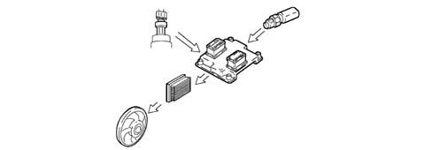
Engine cooling fan check.
Depending on the temperature of the coolant, the Engine Management Node converses with the fan engagement interface to give the go ahead for the:
- engagement of the 1st speed 95°C.
- engagement of the 2nd speed 102°C.
There is then a further check (4 stage pressure switch signal) which switches on the fan at the 1st or 2nd speed depending on the pressure of the refrigerant gas when the air conditioning system is switched on.
If there is no coolant temperature signal, the Engine Management Node implements the recovery function switching on the fan at the 2nd speed via the interface until the fault disappears.
Accelerometric sensor
The accelerometric sensor is a sensor designed to measure acceleration, by means of a piezoelectric element, producing an output voltage that is proportional to the intensity of the actual stress.
It is used to measure the harshness of the ground and for this reason should be installed very firmly on the vehicle body in a precise area: the suspension turret.
The need to measure this harshness value is due to the fact that it is necessary to distinguish between variations in engine torque due to irregularities in the road surface and those due to failed ignition in the combustion chamber (misfire).
The accelerometric sensor is vital in Bosch engine management systems where the ABS does not actively converse with the Bosch Engine Management Node via the high speed CAN line and the uneveness of the ground is distinguished by the speed sensors fitted on the individual wheels.
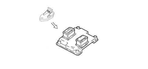
Connection with automatic transmission control unit.
The dialogue between the Engine Management Node and the (automatic) gearbox control unit takes place via the CAN line available at the two control units.
If there is a gear change (signalled by the automatic transmission control unit), the Engine Management Node reduces the engine torque by:
- reducing the ignition advance.
- reducing the throttle opening angle.
Recovery: if the CAN line is faulty, the Engine Management Node does not make the torque reductions requested by the gearbox.
The gearbox control unit implements a specific recovery logic [DF21].
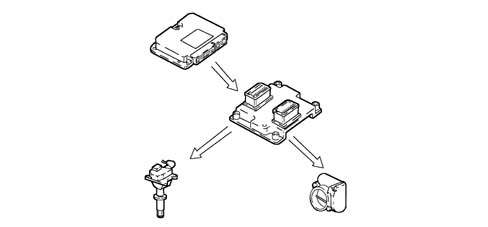
DESCRIPTION OF COMPONENTS.
Engine Management Node.
Specifications.
The Engine Management Node constructed using microhybrid technology, is fitted on the throttle casing and is resistant to high temperatures.
The Engine Management Node memory is the flash EPROM type, i.e. it can be reprogrammed from the outside without affecting the hardware.
The adoption of the encrypted code means that control units cannot be swapped between vehicles.
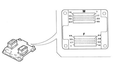
Pin-out.
The Engine Management Node pin out for connector F is as follows:
- F1 - Water temperature warning light check.
- F2 - Cruise Control warning light check.
- F3 - LANCIA CODE control unit connection.
- F4 - Not connected.
- F5 - Not connected.
- F6 - Air conditioning request switch.
- F7 - Accelerator pedal potentiometer supply.
- F8 - Accelerator pedal potentiometer signal pin 1.
- F9 - Quadrinary - 1st speed fan request.
- F10 - Cruise control ON/OFF.
- F11- Automatic transmission signal.
- F12 - Low CAN line.
- F13 - Compressor relay operation.
- F14 - Not connected.
- F15 - +30 Supply.
- F16 - Supply via main relay controlled by ignition.
- F17 - Not connected.
- F17 - Not connected.
- F18 - Not connected F17 - Not connected.
- F19 - Not connected.
- F20 - Not connected.
- F21 - Acceleration sensor signal.
- F22 - Excessive consumption signal.
- F23 - Not connected.
- F24 - Potentiometer earth - accelerator pedal 1.
- F25 - Potentiometer earth - accelerator pedal 2.
- F26 - Brake pedal released signal.
- F27 - Brake pedal pressed signal.
- F28 - Not connected.
- F29 - High CAN line.
- F30 - Fuel pump relay operation.
- F31 - Main relay activation.
- F32 - Supply via main relay controlled by ignition.
- F33 - Not connected.
- F34 - Not connected.
- F35 - Rev counter signal.
- F36 - Not connected.
- F37 - Altitude sensor signal.
- F38 - Not connected.
- F39 - Not connected.
- F40 - Potentiometer signal - accelerator pedal 2.
- F41 - Quadrinary - 2nd speed fan request.
- F42 - Cruise control RCL.
- F43 - Cruise control SET +.
- F44 - Speedometer sensor signal.
- F45 - Not connected.
- F46 - Injection warning light (EOBD)
- F47 - Ignition-operated power supply +15.
- F48 - Power supply via main relay.
- F49 - Not connected.
- F50 - Fan 1st speed signal.
- F51 - Not connected.
- F52 - Fuel consumption signal.
- F53 - Diagnostic connection (K line).
- F54 - Air temperature sensor signal.
- F55 - Not connected.
- F56 - Accelerator pedal potentiometer supply.
- F57 - Air flow meter signal.
- F58 - Cruise control SET -
- F59 - Clutch pedal switch.
- F60 - Oil pressure switch.
- F61 - Not connected.
- F62 - Fan 2nd speed signal.
- F63 - Voltage stabilization sensor.
- F64 - Not connected.
The Engine Management Node pin out for connector M is as follows:
- M1 - Throttle engine supply.
- M2 - Post catalyzer Lambda sensor heating.
- M3 - Cylinder no. 4 injector control.
- M4 - Modular manifold valve.
- M5 - Fuel vapour solenoid valve operation.
- M6 - Detonation sensor 2 reference earth.
- M7 - Not connected.
- M8 - Not connected.
- M9 - Not connected.
- M10 - Engine rpm sensor connector A.
- M11 - Not connected.
- M12 - Not connected.
- M13 - Not connected.
- M14 - Cylinder 3 coil.
- M15 - Cylinder 4 coil.
- M16 - Cylinder 1 coil.
- M17 - Throttle engine supply.
- M18 - Not connected.
- M19 - Cylinder no. 1 injector control.
- M20 - Cylinder no. 3 injector control.
- M21 - EGR valve
- M22 - Detonation sensor 1.
- M23 - Pre-catyalyzer Lambda sensor signal.
- M24 - Potentiometer - 1 throttle casing.
- M25 - Engine coolant temperature sensor.
- M26 - Reference earth for throttle motor.
- M27 - Not connected.
- M28 - Post catalyzer Lambda sensor signal.
- M29 - Not connected.
- M30 - Not connected.
- M31 - Cylinder 5 coil.
- M32 - Cylinder 2 coil.
- M33 - Throttle engine supply.
- M34 - Pre-catalyzer Lambda sensor heating.
- M35 - Cylinder no. 2 injector control.
- M36 - Phase transformer on/off.
- M37 - Not connected.
- M38 - Detonation sensor 2.
- M39 - Not connected.
- M40 - Potentiometer 2 throttle casing.
- M41 - Air pressure sensor.
- M42 - Rpm sensor signal connector A.
- M43 - Not connected.
- M44 - Not connected.
- M45 - Not connected.
- M46 - Not connected.
- M47 - Not connected.
- M48 - Not connected.
- M49 - Throttle engine supply.
- M50 - Not connected.
- M51 - Voltage stabilization sensor 1.
- M52 - Cylinder no. 5 injector control.
- M53 - Excess discharge.
- M54 - Reference earth for detonation sensor 1.
- M55 - Pre-catyalyzer Lambda sensor earth signal
- M56 - Not connected.
- M57 - Air temperature.
- M58 - Throttle potentiometer supply.
- M59 - Engine rpm sensor connector B.
- M60 - Post catalyzer Lambda sensor earth signal.
- M61 - Not connected.
- M62 - Not connected.
- M63 - Not connected.
- M64 - Not connected.
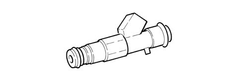
Injectors
Specifications
The twin jet type, they are fitted on the distribution manifold.
A safety clip fastens the injectors to the distribution manifold and two O-Rings ensure the seal.
The injectors are entrusted with the task of supplying the required amount of fuel to the engine.
They are "all or nothing" type devices because they can only assume two stable states, in other words open or closed. They let the fuel pass when they are open and stop the supply when they are closed.
Engine coolant temperature sensor.
Specifications.
It is fitted on the thermostat and measures the temperature of the coolant by means of an NTC twin thermistor with a negative resistance coefficient.
the NTC thermistor sends the signal to the Engine Management Node which sends the signal to the indicator and the warning light in the instrument panel.
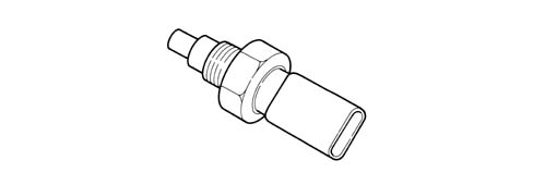
The sensor is designed using semiconductor technology; therefore the resistance level drops if sensor element temperature increases with increasing coolant temperature.
Because the resistance does not change in linear fashion as temperature increases, it is relatively higher at low temperatures than at high temperatures.
Detonation sensors.
Specifications.
The two detonation sensors, which are the piezoresistive type, are fitted at the rear of the cylinder block/crankcase (one between the 1st and 2nd cylinders, the other between the 4th and 5th cylinders) and detect the intensity of the vibrations produced by detonation in the combustion chambers.
The phenomenon produces mechanical repercussions on a piezoelectric crystal which sends a signal to the Engine Management Node.
According to the signal received, the Engine Management Node reduces the ignition advance until the phenomenon disappears. Later on, the advance is gradually restored to the basic value.
The tightening torque for the bolt fixing the detonation sensors is 1.95 -2.05 daNm.

Operation.
The molecules in a quartz crystal feature electrical polarization.
In rest conditions (A:) the molecules do not have a particular orientation.
When the crystal is subject to pressure or to an impact (B) its orientation increases proportionally to the pressure to which it is subjected. This orientation produces a voltage at the ends of the crystal.
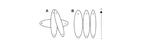
- A, Rest position.
- B, Position under pressure.
Rpm sensor.
Specifications.
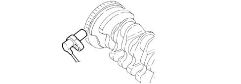
It is fitted on the cylinder block/crankcase facing the flywheel on the crankshaft.
The sensor is inductive type, i.e. it uses changes in the magnetic field generated by the phonic wheel teeth (60-2 teeth) passing in front of the sensor element.
The Engine Management Node uses the rpm sensor signal to determine the rotation speed and to determine the angular position of the crankshaft.
Operation.
The changeover from full to empty determined by the presence or absence of a gap brings about a magnetic flux change sufficient to generate an induced alternating voltage proportional to the number of holes on the phonic wheel.
The frequency and amplitude of the voltage sent to the Engine Management Node provides the measurement of the engine angular speed.
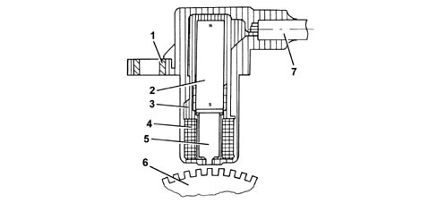
- 1 Brass bush.
- 2 Permanent magnet.
- 3 Plastic sensor casing.
- 4 Coil winding.
- 5 Core.
- 6 Ring gear or flywheel.
- 7 Coaxial twin wire cable or electrical connection.
The recommended distance (gap) between the end of the sensor and the flywheel for obtaining correct signals should be between 0.8 ¸ 1.5 mm.
This distance is not adjustable. If the gap is found to be outside the tolerance limits, check the condition of the sensor and phonic wheel.
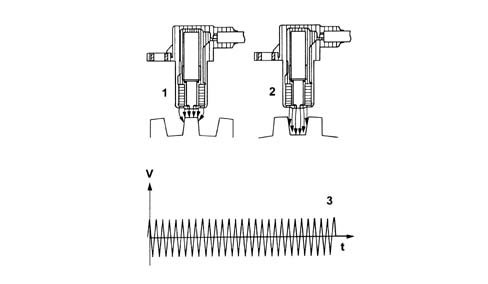
- 1 Maximum magnetic flux.
- 2 Minimum magnetic flux.
- 3 Induced alternating voltage.
Timing sensor.
Specifications.
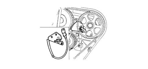
This Hall effect sensor is fitted on the cylinder head facing the (exhaust) camshaft drive pulley.
D.V.E.integrated throttle casing
Specifications
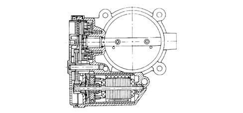
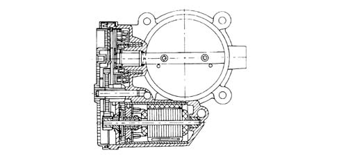
It is fitted on the intake chamber and regulates the quantity of air drawn in by the engine.
Depending on the signal coming from the accelerator pedal potentiometer, the Engine Management Node controls the opening of the throttle by means of a direct current motor incorporated in the D.V.E. throttle casing.
The throttle opening takes place between 0° and 80° including the adjustment of the idle speed.
The D.V.E. throttle casing is fitted with two built in potentiometers so that one controls the other and viceversa.
If there is a problem with the two potentiometers or no supply, depending on the position of the accelerator pedal, the Engine Management Node reduces the engine torque:
- with the pedal fully depressed, it cuts off the supply to one or more pistons until a maximum speed of 2500 rpm is reached;
- with the pedal in a halfway position, it cuts off the supply to one or more pistons until a lower speed of 2500 rpm is reached.
If the D.V.E. throttle casing is replaced then the self-learning procedure has to be carried out.
Air flow meter with built in air temperature sensor
Specifications.
The flow meter is located on the air intake hose and is hot film type.
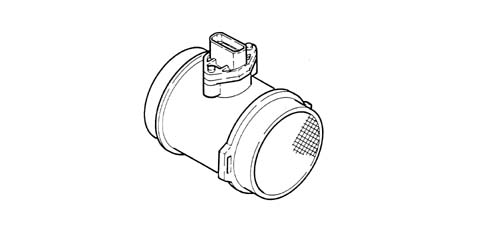
The intake air temperature sensor is incorporated in the flow meter.
The air flow meter cannot be dismantled.
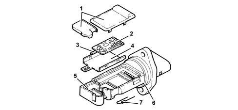
- 1 Covers.
- 2 Electronic card.
- 3 Sensor.
- 4 Mounting plate.
- 5 Mount.
- 6 O - Ring seal.
- 7 Temperature sensor.
Operation
The principle of operation is based on a heated membrane positioned within a measurement channel that carries air into the engine.
The hot film membrane is maintained at constant temperature (about 120°C higher than the incoming air temperature) by the heating coil.
The air mass that flows through the measurement channel tends to remove heat from the membrane. Current must therefore flow through the coil to maintain the membrane at a constant temperature.
This current is measured usign a suitable Wheatstone bridge.
The current is therefore proportional to the mass of air.
The flow meter measures the mass of air (not the volume) directly, thereby eliminating problems of temperature, altitude, pressure, etc.
Ignition coils.
Specifications.
The ignition circuit is the static advance, inductive discharge type where the high tension is provided by five coils fitted directly on the spark plugs (pencil coils).
The coil used is the closed magnetic circuit type with the windings housed in a plastic container immersed in epoxide resin. The coil is connected directly to the spark plug by means of a silicon extension with very good dielectric properties.
The coil incorporates the power transistor for interrupting the primary winding.
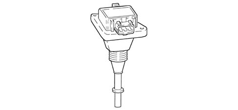
Operation.
The primary winding for each coil receives a battery voltage supply (+30) via the twin relay and is earthed through the power transistor whose base is connected to the appropriate Engine Management Node pin.
Interrupting the current at the base of the transistor interrupts the connection to earth of the primary winding and, consequently, causes a high tension discharge at the secondary winding.
The optimum ignition advance is calculated by the Engine Management Node depending on the engine load and speed and is implemented in the form of the time between TDC in the explosion stroke and the moment the supply for the coil primary winding circuit is interrupted.
Accelerator pedal potentiometer.
Specifications.
The accelerator pedal is equipped with two integral potentiometers, a main one and a safety one.
The Engine Control Node implements the following recovery strategies.
- if one of the two potentiometers fails, this allows the throttle to be opened to a maximum of 40° over a long time period;
- if both potentiometers fail completely, it prevents throttle opening.
Composition.
The sensor consists of a case secured to the pedal unit by a flange. This contains an axially-located shaft connected to a dual-track potetiometer.
A coil spring on the shaft ensures the correct amount of resistance to pressure while a second spring ensures return following release.
Operating field from 0° to 70°; mechanical stop at 88°.
If one or both potentiometers fail, the whole accelerator pedal must be replaced because it cannot be dismantled.
SPECIFICATIONS
Function
The Bosch Motronic system belongs the category of systems integrated with:
- inductive discharge, digital, electronic ignition.
- static advance.
- sequential, phased type electronic injection (1-2-4-5-3).
The Engine Management Node controls:
- the air flow rate whilst idling set via the electronic throttle;
- the moment of ignition with the advantage of the engine running smoothly as the environmental parameters and loads applied vary.
The Engine Management Node controls and manages the injection so that the air/fuel ratio is always very close to the stoichiometric value in order to ensure maximum conversion efficiency for the catalyzer; in full power and high usage conditions the mixture is enirched to guarantee maximum performance.
The main functions of the system are basically as follows:
- self-learning;
- system self-adjustment;
- self-diagnosis;
- CODE recognition;
- cold starting check;
- combustion - Lambda sensor check
- check on phase transformer and modular intake manifold;
- knock control;
- check on enrichment during acceleration;
- fuel cut-off when accelerator pedal is released;
- fuel vapour recovery;
- maximum rpm check;
- fuel supply - electric fuel pump check;
- connection with climate control system;
- recognition of cylinder position;
- injection time adjustment;
- ignition advance adjustment;
- idle speed check;
- control of engine cooling fan;
- connection with automatic transmission control unit (where fitted);
- connection with ABS control unit;
- connection with control panel.
- fuel system fault diagnosis;
- catalyzer fault diagnosis.
- Lambda sensor fault diagnosis.
- misfire fault diagnosis
VIEW OF ASSEMBLY.
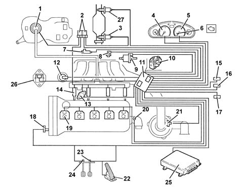
- 1 Fuel pump.
- 2 Relays.
- 3 Lambda sensor (upstream).
- 4 Speedometer.
- 5 Rev counter.
- 6 Injection warning light.
- 7 Knock sensors.
- 8 RPM sensor.
- 9 Fuel vapour recirculation solenoid.
- 10 Throttle body built into DVE
- 11 Engine Management Node.
- 12 Modular intake manifold solenoid.
- 13 Phase transformer.
- 14 Injectors.
- 15 Climate control system connector.
- 16 Tester connector.
- 17 CODE connector.
- 18 Timing sensor.
- 19 Ignition coils.
- 20 Coolant temperature sensor.
- 21 Air flow meter with air temperature sensor.
- 22 Accelerator pedal potetiometer.
- 23 Brake pedal switch.
- 24 Clutch pedal switch.
- 25 Automatic transmission control unit (where necessary).
- 26 Engine coolant temperature control unit.
- 27 Lambda sensor (downstream).
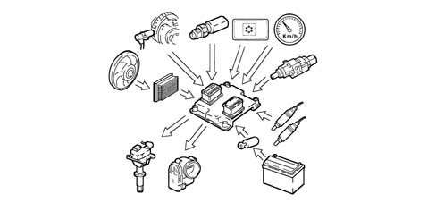
DIAGRAM SHOWING INFORMATION ENTERING/LEAVING ENGINE MANAGEMENT NODE.
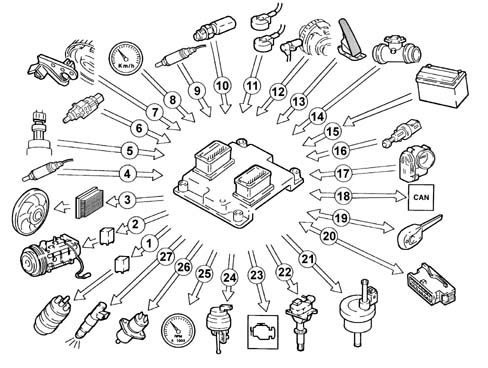
- 1 Fuel pump.
- 2 Air conditioning compressor.
- 3 Fan.
- 4 Lambda sensors downstream of the catalytic converter.
- 5 Quadrinary
- 6 Brake pedal switch.
- 7 Timing sensor.
- 8 Speedometer.
- 9 Lambda sensor upstream of the pre-catalyzer.
- 10 Coolant temperature sensor.
- 11 Knock sensor (two).
- 12 RPM sensor.
- 13 Accelerator pedal potetiometer.
- 14 Air flow meter with air temperature sensor.
- 15 Battery.
- 16 Clutch pedal switch.
- 17 Throttle body built into DVE
- 18 CAN line (for communication with ABS/ASR control units).
- 19 Lancia CODE.
- 20 Diagnotic socket.
- 21 Fuel vapour recirculation solenoid.
- 22 Ignition coils.
- 23 Injection warning light.
- 24 Modular intake manifold solenoid.
- 25 Rev counter.
- 26 Phase transformer.
- 27 Injectors
OPERATION
Operating strategies
General remarks
Injection system
The following conditions are essential and must always be satisfied during the preparation of the air/fuel mixture for the smooth operation of ignition controlled engines:
- the "metering" (air/fuel ratio) must be kept as close as possible to the stoichiometric value to ensure the maximum conversion capacity of the catalytic converters (max. efficiency).
- the "homogoneity" of the mixture, composed of petrol dispersed in the air as finely and evenly as possible.
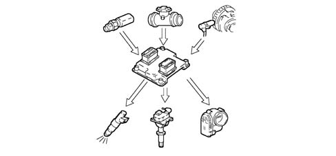
The information that the Engine Management Node processes for optimum metering is received via electrical signals transmitted by the:
- air flow meter and air temperature sensor for the exact quantity of intake air.
- rpm sensor which produces an alternating, single phase signal whose frequency indicates the engine speed. This signal is used by the Engine Management Node for detecting misfire.
- throttle potentiometer to recognize the acceleration conditions requested.
- coolant temperature sensor located on the thermostat.
- Lambda sensors to determine the oxygen content of the exhaust gases and, via the downstream sensor, to diagnose the efficiency of the catalyzers.
Ignition system.
The ignition system is the static advance, inductive discharge type (i.e. with no high tension distributor) with power modules located inside the Engine Management Node.
In this ignition system each coil supplies the spark plugs for the appropriate cylinder.
The advantages of this solution are:
- less electrical overload;
- guaranteed constant discharge at each spark plug.
A map is stored in the Engine Management Node memory which contains the series of optimum ignition advance values (for the cylinder in the explosion stroke) which the engine can adopt according to the engine load and speed conditions.
The Engine Management Node makes corrections to the advance value mainly according to the:
- engine coolant temperature.
- intake air temperature.
- detonation.
- throttle valve position.
The information that the Engine Management Node processes to operate the coils is received via electrical signals transmitted by the:
- air flow meter with built in air temperature sensor for the exact quantity of intake air.
- rpm sensor which produces an alternating, single phase signal whose frequency indicates the engine speed.
- 2 detonation sensors (at the rear of the cylinder block/crankcase, one between the 1st and 2nd cylinders, the other between the 4th and 5th) to recognize which cylinder detonation is taking place in and therefore correct the ignition advance.
- throttle position potentiometer to recognize minimum load, partial load and full gas conditions.
- timing sensor.
Self-learning.
The Engine Management Node implements the self-learning logic in the following conditions:
removing-refitting or replacing the Engine Management Node.
removing-refitting or replacing the throttle casing.
The values memorized by the Engine Management Node are preserved if the battery is disconnected.
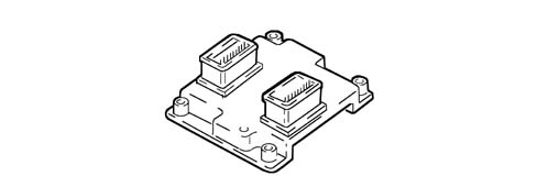
System self-adjustment.
The Engine Management Node is equipped with a self-adjustment function that is designed to recognize the changes that take place in the engine due to the processes of bedding in and ageing of both the components and the engine itself in time.
These changes are memorized in the form of modifications to the basic map and are designed to adapt the operation of the system to the gradual alterations in the engine and the components compared with when they were new.
This self-adjustment function also makes it possible to compensate for the inevitable differences in any replacement components (due to production tolerances).
From the analysis of the exhaust gases, the Engine Management Node modifies the basic map in relation to the specifications of the engine when new.
The self-adjustment parameters are not cancelled if the battery is disconnected.

Self-diagnosis
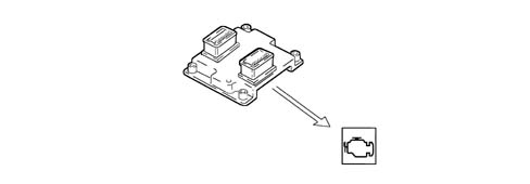
The Engine Management Node checks that the system is working properly and signals any irregularities by means of an MIL warning light in the instrument panel with a standardized ideogram and colour laid down by European regulations. This warning light signals both engine management faults and defects detected by the EOBD strategies.
The MIL warning light operating logic is as follows:
- with the ignition on, the warning light comes on and remains on until the engine has been started up. The Engine Management Node autodiagnostic system checks the signals coming from the sensors comparing them with the permitted limits:
Siganalling of faults during stating:
- the failure of the warning light to go out when the engine has been started indicates that there is an error memorized in the Engine Management Node.
Signalling of faults during operation:
- the warning light flashing indicates possible damage to the catalyzer through the presence of misfire.
- the warning light coming on constantly indicates the presence of engine management errors or EOBD errors.
RECOVERY
From time to time the Engine Management Node defines the type of recovery according to the components that are faulty. The recovery parameters are managed by components that are not faulty.
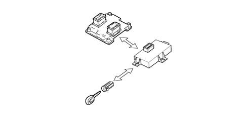
CODE recognition
The moment the Body Computer receives the ignition ON signal, it converses with the Engine Management Node to allow starting. For vehicles equipped with Passive Entry see {DF55].
Cold starting check.
The following occurs in cold starting conditions:
- a natural weakening of the mixture which causes poor evaporation (poor turbulence of the particles of fuel at low temperatures).
- reduced evaporation of the fuel.
- condensation of the fuel on the inner walls of the intake manifold.
- increased viscosity of the lubrication oil.
The Engine Management Node recognizes this condition and corrects the basic injection time:
- coolant temperature.
- intake air temperature.
- battery voltage.
- engine speed.
The ignition advance only depends on the number of revs and the temperature of the engine coolant.
Whilst the engine is warming up, the Engine Management Node operates the motorized throttle to regulate the quantity of air required to ensure that the engine does not cut out.
The rotation speed decreases proportionally as the engine temperature increases until the nominal value is reached when the engine has warmed up.
Combustion - Lambda sensor check.
In EOBD systems, the Lambda sensors, which are all the same type, are located upstream of the catalyzer system and downstream of the catalyzer. The upstream sensor determines the control of the mixture strength known as the 1st closed loop for the upstream sensor. The sensor downstream of the catalyzer is used for the fault diagnosis of the catalyzer and for modulating the 1st loop control parameters. The adaptation of the second loop is designed to recover both production dispersions and the slight deviations in the response of the upstream sensors as a result of ageing or pollution. This control is known as the 2nd closed loop of the downstream sensor).
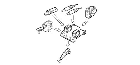
Check on phase transformer and modular intake manifold
In order to ensure the optimum quantity of air introduced by the engine, the Engine Management Node controls:
- the intake timing in two angular positions.
- the geometry of the intake manifolds in two lengths.
The Engine Management Node sets the "open" stage at the maximum torque speed:
- cam advance of 18° engine.
- intake chamber long ducts.
The Engine Management Node sets the "closed" stage at the maximum power speed and the minimum speed:
- cam in normal position.
- intake chamber short ducts.
In the other engine operating conditions, the Engine Management Node selects the most suitable configuration for optimum performance, consumption and emissions.
In the release stage the chamber intake ducts are always short. In the release stage the chamber intake ducts are always short.
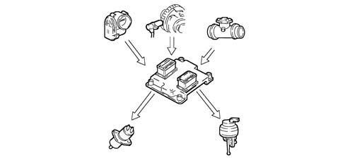
Knock control.
The Engine Management Node detects the presence of detonation (engine knock) by processing the signal coming from the relevant sensors.
The Engine Management Node continuously compares the signals coming from the sensors with a threshold which is, in turn, continually updated to take into account background noise and engine ageing.
The Engine Management Node is therefore capable of detecting the presence of detonation (or the onset of detonation) in each individual cylinder and reduces the ignition advance in the cylinder involved (in steps of 3° up to a maximum of 6°) until the phenomenon disappears. Later on, the advance is gradually restored to the basic value (in steps of 0.8°).
In acceleration conditions, a higher threshold is used to take into account the increased noise of the engine in these circumstances.
The detonation control logic also has a self-adjustment function which memorizes the reductions in the advance that are continuously repeated in order to adapt the map to the different conditions that the engine finds itself in.
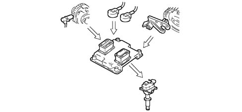
Check on enrichment during acceleration.
If the variation in the air flow meter signal exceeds a pre-defined increase during an acceleration request, the Engine Management Node increases the injection (injection time) in order to reach the required number of revs rapidly.
Recovery:
the Engine Management Node replaces the signal coming from the air flow meter which is faulty with the throttle potentiometer signal.
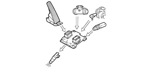
Fuel cut off during over-run (cut-off)
When the accelerator pedal is released and beyond a pre-set engine speed level, the Engine Management Node:
- cuts off the supply to the injectors.
- reactivates the supply to the injectors at 1300 ¸ 1500 rpm
If there is no supply, the number of revs decreases with the speed depending on the vehicle driving conditions.
Before the idle speed is reached, the progress of the engine speed decrease is checked.
If it is above a certain value, the fuel supply is partly restored so that there is a "gentle accompaniment" towards the idle speed.
The levels for restoring the supply and for cutting off the fuel vary according to:
- engine coolant temperature.
- vehicle speed.
- engine rpm.
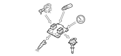
Fuel vapour recovery.
The petrol vapours developed in the tank are collected in a separator which condenses them as much as possible directing them to the tank via suitable ducts.
The remaining vapours are absorbed by a charcoal filter (canister) from where they can be drawn in and burnt by the engine during the appropriate stages.
This is managed by means of a solenoid valve which opens and closes the duct towards the intake chamber.
The Engine Management Node implements an adjustment strategy by controlling the value supplied by the Lambda sensor during the canister scrubbing stages:
- if there is excess oxygen in the composition of the exhaust gases (lean mixture), this means that there are no petrol vapours present in the canister and therefore the solenoid valve is closed after a short time;
- if the mixture is enriched, the Engine Management Node keeps the solenoid valve open, allowing the scrubbing of the filter and adjusting the injection time. The opening is maintained until the variation in the mixture is detected (lean condition) and then it is closed again. The filter scrubbing capacity is nominally limited to percentage points of the air flow meter reading so that there is a balance and the driveability of the vehicle is disturbed as little as possible.
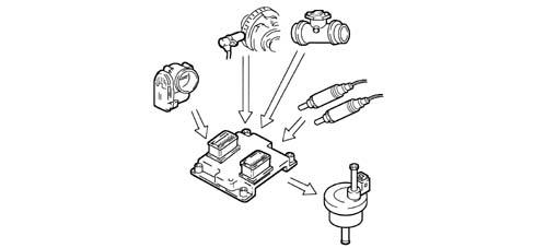
Maximum rpm check.
Depending on the speed reached by the engine, the Engine Management Node:
- above 6800 rpm, cuts off the supply to the injectors (a maximum of 7200 rpm can be reached for not more than 3 secs.).
- below 6800 rpm, the operation of the injectors is restored.
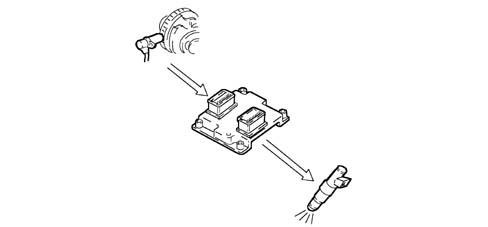
Fuel supply - electric fuel pump check
The Engine Management Node supplies the pump:
- with the ignition ON for 0.8 secs.
- with the ignition in AVV and the engine speed > 22.8 rpm
The Engine Management Node interrupts the supply to the pump:
- with the key in OFF position.
- with the engine speed < 22.8 rpm.
The returnless fuel supply system ensures a constant pressure of 3.5 bar.
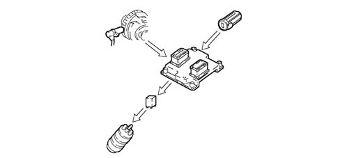
Connection with climate control system.
When there is a request for power due to the compressor having been switched on, the Engine Management Node operates the throttle to increase the air flow rate.
The Engine Management Node momentarily interrupts the supply to the compressor:
- during starting.
- switching it off beyond 6200 rpm.
- switching it off when the engine temperature is > 112°C.
- during take off with the accelerator fully depressed.
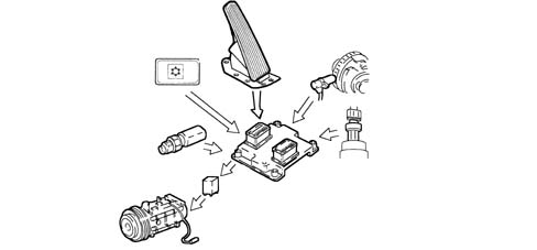
Recognition of cylinder position.
During each revolution of the engine the Engine Management Node recognizes which cylinder is in the explosion stroke and controls the ignition and the injection sequence at the appropriate cylinder.
If there is no timing sensor signal, the Engine Management Node:
- deactivates the detonation sensors.
- maintains the phased injection with the vehicle moving.
- the vehicle does not start with the timing sensor broken.
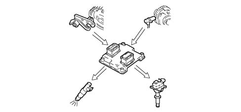
Injection time adjustment
The Engine Management Node calculates the injector opening time and controls them with extreme precision and speed depending on the:
- engine load (number of revs and air flow rate).
- battery voltage.
- engine coolant temperature.
The injection is the phased, sequential type for each cylinder and takes place corresponding to the optimum injection point "start of injection", with the "end of injection" point remaining fixed.
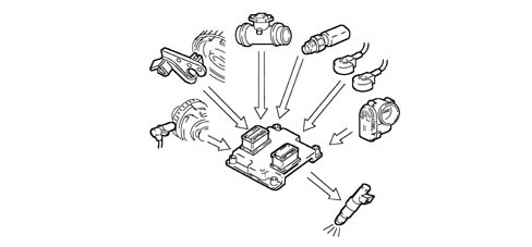
Ignition advance adjustment.
Thanks to a map stored in its memory, the Engine Management Node is capable of calculating the ignition advance depending on:
- the engine load (minimum, partial, full, according to the number of revs and the air flow rate).
- the intake air temperature.
- the engine coolant temperature.
The ignition can be selectively delayed at the cylinder required, recognized through the combination of values recorded by the rpm and timing sensors.
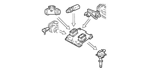
Idle speed check.
The Engine Management Node recognizes the minimum condition through the accelerator pedal being in the "released" position.
To control the idle speed, depending on the consumers switched on and the brake/clutch pedal signals, the Engine Management Node controls the position of the motorized throttle.
The idle speed when warm is 700 ± 50 rpm with the air conditioning switched off; with the air conditioning switched on the idle speed is 770 ± 50 rpm.
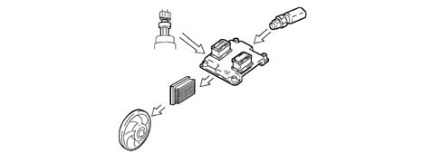
Engine cooling fan check.
Depending on the temperature of the coolant, the Engine Management Node converses with the fan engagement interface to give the go ahead for the:
- engagement of the 1st speed 95°C.
- engagement of the 2nd speed 102°C.
There is then a further check (4 stage pressure switch signal) which switches on the fan at the 1st or 2nd speed depending on the pressure of the refrigerant gas when the air conditioning system is switched on.
If there is no coolant temperature signal, the Engine Management Node implements the recovery function switching on the fan at the 2nd speed via the interface until the fault disappears.
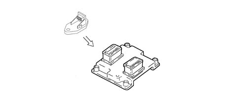
Accelerometric sensor
The accelerometric sensor is a sensor designed to measure acceleration, by means of a piezoelectric element, producing an output voltage that is proportional to the intensity of the actual stress.
It is used to measure the harshness of the ground and for this reason should be installed very firmly on the vehicle body in a precise area: the suspension turret.
The need to measure this harshness value is due to the fact that it is necessary to distinguish between variations in engine torque due to irregularities in the road surface and those due to failed ignition in the combustion chamber (misfire).
The accelerometric sensor is vital in Bosch engine management systems where the ABS does not actively converse with the Bosch Engine Management Node via the high speed CAN line and the uneveness of the ground is distinguished by the speed sensors fitted on the individual wheels.
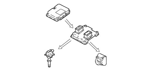
Connection with automatic transmission control unit.
The dialogue between the Engine Management Node and the (automatic) gearbox control unit takes place via the CAN line available at the two control units.
If there is a gear change (signalled by the automatic transmission control unit), the Engine Management Node reduces the engine torque by:
- reducing the ignition advance.
- reducing the throttle opening angle.
Recovery: if the CAN line is faulty, the Engine Management Node does not make the torque reductions requested by the gearbox.
The gearbox control unit implements a specific recovery logic [DF21].
DESCRIPTION OF COMPONENTS
Engine Management Node
Specifications
The Engine Management Node constructed using microhybrid technology, is fitted on the throttle casing and is resistant to high temperatures.
The Engine Management Node memory is the flash EPROM type, i.e. it can be reprogrammed from the outside without affecting the hardware.
The adoption of the encrypted code means that control units cannot be swapped between vehicles.
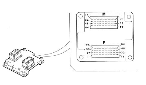
Pin-out.
The Engine Management Node pin out for connector F is as follows:
- F1 - Water temperature warning light check.
- F2 - Cruise Control warning light check.
- F3 - LANCIA CODE control unit connection.
- F4 - Not connected.
- F5 - Not connected.
- F6 - Air conditioning request switch.
- F7 - Accelerator pedal potentiometer supply.
- F8 - Accelerator pedal potentiometer signal pin 1.
- F9 - Quadrinary - 1st speed fan request.
- F10 - Cruise control ON/OFF.
- F11- Automatic transmission signal.
- F12 - Low CAN line.
- F13 - Compressor relay operation.
- F14 - Not connected.
- F15 - +30 Supply.
- F16 - Supply via main relay controlled by ignition.
- F17 - Not connected.
- F18 - Not connected.
- F19 - Not connected.
- F20 - Not connected.
- F21 - Acceleration sensor signal.
- F22 - Excessive consumption signal.
- F23 - Not connected.
- F24 - Potentiometer earth - accelerator pedal 1.
- F25 - Potentiometer earth - accelerator pedal 2.
- F26 - Brake pedal released signal.
- F27 - Brake pedal pressed signal.
- F28 - Not connected.
- F29 - High CAN line.
- F30 - Fuel pump relay operation.
- F31 - Main relay activation.
- F32 - Supply via main relay controlled by ignition.
- F33 - Not connected.
- F34 - Not connected.
- F35 - Rev counter signal.
- F36 - Not connected.
- F37 - Altitude sensor signal.
- F38 - Not connected.
- F39 - Not connected.
- F40 - Potentiometer signal - accelerator pedal 2.
- F41 - Quadrinary - 2nd speed fan request.
- F42 - Cruise control RCL.
- F43 - Cruise control SET +.
- F44 - Speedometer sensor signal.
- F45 - Not connected.
- F46 - Injection warning light (EOBD)
- F47 - Ignition-operated power supply +15.
- F48 - Power supply via main relay
- F49 - Not connected.
- F50 - Fan 1st speed signal.
- F51 - Not connected.
- F52 - Fuel consumption signal.
- F53 - Diagnostic connection (K line).
- F54 - Air temperature sensor signal.
- F55 - Not connected.
- F56 - Accelerator pedal potentiometer supply.
- F57 - Air flow meter signal.
- F58 - Cruise control SET -
- F59 - Clutch pedal switch.
- F60 - Oil pressure switch.
- F61 - Not connected.
- F62 - Fan 2nd speed signal.
- F63 - Voltage stabilization sensor.
- F64 - Not connected.
The Engine Management Node pin out for connector M is as follows:
- M1 - Throttle engine supply.
- M2 - Post catalyzer Lambda sensor heating.
- M3 - Cylinder no. 4 injector control.
- M4 - Modular manifold valve.
- M5 - Fuel vapour solenoid valve operation.
- M6 - Detonation sensor 2 reference earth.
- M7 - Not connected.
- M8 - Not connected.
- M9 - Not connected.
- M10 - Engine rpm sensor connector A.
- M11 - Not connected.
- M12 - Not connected.
- M13 - Not connected.
- M14 - Cylinder 3 coil.
- M15 - Cylinder 4 coil.
- M16 - Cylinder 1 coil.
- M17 - Throttle engine supply.
- M18 - Not connected.
- M19 - Cylinder no. 1 injector control.
- M20 - Cylinder no. 3 injector control.
- M21 - EGR valve
- M22 - Detonation sensor 1.
- M23 - Pre-catyalyzer Lambda sensor signal
- M24 - Potentiometer - 1 throttle casing.
- M25 - Engine coolant temperature sensor.
- M26 - Reference earth for throttle motor.
- M27 - Not connected.
- M28 - Post catalyzer Lambda sensor signal.
- M29 - Not connected.
- M30 - Not connected.
- M31 - Cylinder 5 coil.
- M32 - Cylinder 2 coil.
- M33 - Throttle engine supply.
- M34 - Pre-catalyzer Lambda sensor heating.
- M35 - Cylinder no. 2 injector control.
- M36 - Phase transformer on/off.
- M37 - Not connected.
- M38 - Detonation sensor 2.
- M39 - Not connected.
- M40 - Potentiometer 2 throttle casing.
- M41 - Air pressure sensor.
- M42 - Rpm sensor signal connector A.
- M43 - Not connected.
- M44 - Not connected.
- M45 - Not connected.
- M46 - Not connected.
- M47 - Not connected.
- M48 - Not connected.
- M49 - Throttle engine supply.
- M50 - Not connected.
- M51 - Voltage stabilization sensor 1.
- M52 - Cylinder no. 5 injector control.
- M53 - Excess discharge.
- M54 - Reference earth for detonation sensor 1.
- M55 - Pre-catyalyzer Lambda sensor earth signal
- M56 - Not connected.
- M57 - Air temperature.
- M58 - Throttle potentiometer supply.
- M59 - Engine rpm sensor connector B.
- M60 - Post catalyzer Lambda sensor earth signal.
- M61 - Not connected.
- M62 - Not connected.
- M63 - Not connected.
- M64 - Not connected.
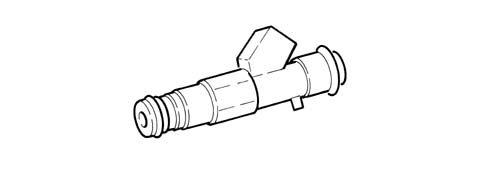
Injectors
Specifications
The twin jet type, they are fitted on the distribution manifold.
A safety clip fastens the injectors to the distribution manifold and two O-Rings ensure the seal.
The injectors are entrusted with the task of supplying the required amount of fuel to the engine.
They are "all or nothing" type devices because they can only assume two stable states, in other words open or closed. They let the fuel pass when they are open and stop the supply when they are closed.
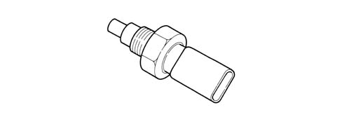
Engine coolant temperature sensor.
Specifications
It is fitted on the thermostat and measures the temperature of the coolant by means of an NTC twin thermistor with a negative resistance coefficient.
the NTC thermistor sends the signal to the Engine Management Node which sends the signal to the indicator and the warning light in the instrument panel.
The sensor is designed using semiconductor technology; therefore the resistance level drops if sensor element temperature increases with increasing coolant temperature.
Because the resistance does not change in linear fashion as temperature increases, it is relatively higher at low temperatures than at high temperatures.
Detonation sensors.
Specifications
The two detonation sensors, which are the piezoresistive type, are fitted at the rear of the cylinder block/crankcase (one between the 1st and 2nd cylinders, the other between the 4th and 5th cylinders) and detect the intensity of the vibrations produced by detonation in the combustion chambers.
The phenomenon produces mechanical repercussions on a piezoelectric crystal which sends a signal to the Engine Management Node.
According to the signal received, the Engine Management Node reduces the ignition advance until the phenomenon disappears. Later on, the advance is gradually restored to the basic value.
The tightening torque for the bolt fixing the detonation sensors is 1.95 -2.05 daNm.

Operation
The molecules in a quartz crystal feature electrical polarization.
In rest conditions (A:) the molecules do not have a particular orientation.
When the crystal is subject to pressure or to an impact (B) its orientation increases proportionally to the pressure to which it is subjected. This orientation produces a voltage at the ends of the crystal.
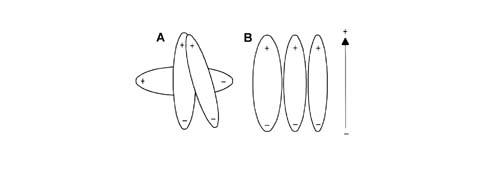
- A, Rest position.
- B, Position under pressure.
Rpm sensor.
Specifications
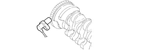
It is fitted on the cylinder block/crankcase facing the flywheel on the crankshaft.
The sensor is inductive type, i.e. it uses changes in the magnetic field generated by the phonic wheel teeth (60-2 teeth) passing in front of the sensor element.
The Engine Management Node uses the rpm sensor signal to determine the rotation speed and to determine the angular position of the crankshaft.
Operation
The changeover from full to empty determined by the presence or absence of a gap brings about a magnetic flux change sufficient to generate an induced alternating voltage proportional to the number of holes on the phonic wheel.
The frequency and amplitude of the voltage sent to the Engine Management Node provides the measurement of the engine angular speed.
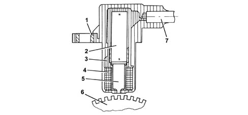
- 1 Brass bush.
- 2 Permanent magnet.
- 3 Plastic sensor casing.
- 4 Coil winding.
- 5 Core.
- 6 Ring gear or flywheel.
- 7 Coaxial twin wire cable or electrical connection.
The recommended distance (gap) between the end of the sensor and the flywheel for obtaining correct signals should be between 0.8 ÷ 1.5 mm.
This distance is not adjustable. If the gap is found to be outside the tolerance limits, check the condition of the sensor and phonic wheel.
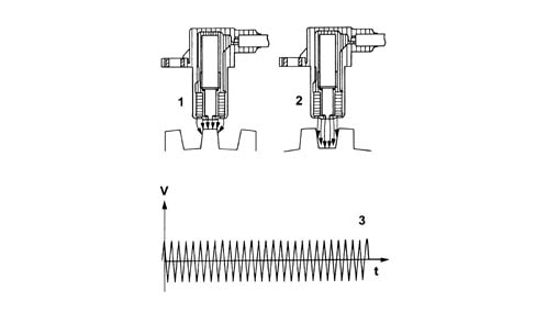
- 1 Maximum magnetic flux.
- 2 Minimum magnetic flux.
- 3 Induced alternating voltage.
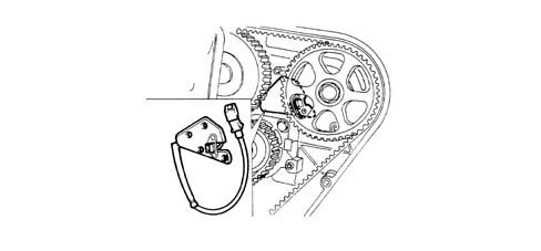
Timing sensor
Specifications
This Hall effect sensor is fitted on the cylinder head facing the (exhaust) camshaft drive pulley.
D.V.E.integrated throttle casing
Specifications
It is fitted on the intake chamber and regulates the quantity of air drawn in by the engine.
Depending on the signal coming from the accelerator pedal potentiometer, the Engine Management Node controls the opening of the throttle by means of a direct current motor incorporated in the D.V.E. throttle casing.
The throttle opening takes place between 0° and 80° including the adjustment of the idle speed.
The D.V.E. throttle casing is fitted with two built in potentiometers so that one controls the other and viceversa.
If there is a problem with the two potentiometers or no supply, depending on the position of the accelerator pedal, the Engine Management Node reduces the engine torque:
- with the pedal fully depressed, it cuts off the supply to one or more pistons until a maximum speed of 2500 rpm is reached;
- with the pedal in a halfway position, it cuts off the supply to one or more pistons until a lower speed of 2500 rpm is reached.
If the D.V.E. throttle casing is replaced then the self-learning procedure has to be carried out.
Air flow meter with built in air temperature sensor
Specifications
The flow meter is located on the air intake hose and is hot film type.
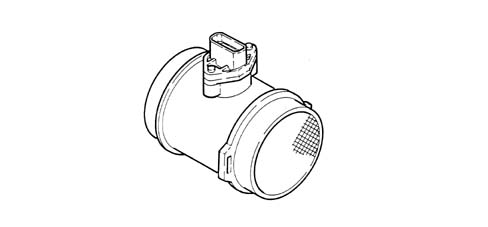
The intake air temperature sensor is incorporated in the flow meter.
The air flow meter cannot be dismantled.
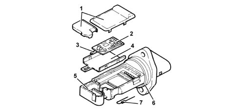
- 1 Covers.
- 2 Electronic card.
- 3 Sensor.
- 4 Mounting plate.
- 5 Mount.
- 6 O - Ring seal.
- 7 Temperature sensor.
Operation
The principle of operation is based on a heated membrane positioned within a measurement channel that carries air into the engine.
The hot film membrane is maintained at constant temperature (about 120°C higher than the incoming air temperature) by the heating coil.
The air mass that flows through the measurement channel tends to remove heat from the membrane. Current must therefore flow through the coil to maintain the membrane at a constant temperature.
This current is measured usign a suitable Wheatstone bridge.
The current is therefore proportional to the mass of air.
The flow meter measures the mass of air (not the volume) directly, thereby eliminating problems of temperature, altitude, pressure, etc.
Ignition coils
Specifications
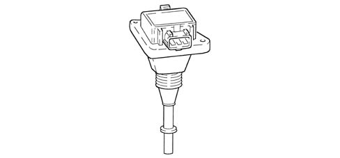
The ignition circuit is the static advance, inductive discharge type where the high tension is provided by five coils fitted directly on the spark plugs (pencil coils).
The coil used is the closed magnetic circuit type with the windings housed in a plastic container immersed in epoxide resin. The coil is connected directly to the spark plug by means of a silicon extension with very good dielectric properties.
The coil incorporates the power transistor for interrupting the primary winding.
Operation
The primary winding for each coil receives a battery voltage supply (+30) via the twin relay and is earthed through the power transistor whose base is connected to the appropriate Engine Management Node pin.
Interrupting the current at the base of the transistor interrupts the connection to earth of the primary winding and, consequently, causes a high tension discharge at the secondary winding.
The optimum ignition advance is calculated by the Engine Management Node depending on the engine load and speed and is implemented in the form of the time between TDC in the explosion stroke and the moment the supply for the coil primary winding circuit is interrupted.
Accelerator pedal potentiometer.
Specifications
The accelerator pedal is equipped with two integral potentiometers, a main one and a safety one.
The Engine Control Node implements the following recovery strategies.
- if one of the two potentiometers fails, this allows the throttle to be opened to a maximum of 40° over a long time period;
- if both potentiometers fail completely, it prevents throttle opening.
Composition
The sensor consists of a case secured to the pedal unit by a flange. This contains an axially-located shaft connected to a dual-track potetiometer.
A coil spring on the shaft ensures the correct amount of resistance to pressure while a second spring ensures return following release.
Operating field from 0° to 70°; mechanical stop at 88°.
If one or both potentiometers fail, the whole accelerator pedal must be replaced because it cannot be dismantled.
SPECIFICATIONS
Function
The Bosch Motronic belongs the category of systems integrated with:
- ignition.
- phased sequential electronic injection.
The Engine Control Node controls:
- air flow at the idling speed set by the electronic throttle;
- ignition time, with the benefit of maintaining smooth engine operation even when environmental and applied load parameters change.
The Engine Control Node controls and manages injection so that stoichiometric air/fuel ratio is always within optimum limits.
Main system functions are essentially as follows:
- self-learning;
- system self-adaptation;
- self-diagnosis;
- Lancia CODE recognition;
- cold starting check control;
- Combustion - Lambda sensor control;
- knock control;
- control of enrichment during acceleration;
- Fuel cut-off during over-run;
- fuel vapour recovery;
- control of maximum rpm;
- fuel pump control;
- Connection with climate control system;
- cylinder position recognition;
- control of optimum injection time for each cylinder;
- Ignition advance adjustment;
- idle speed management (also dependent on battery voltage);
- throttle opening law management (Sport throttle reponse);
- control of engine cooling fan;
- control of Cruise control system;
- connection to ABS control unit;
- connection with automatic transmission control unit;
- connection with control panel.
- fuel system diagnostics;
- catalytic converter diagnostics;
- misfire detection;
- lambda sensor diagnostics.
VIEW OF ASSEMBLY
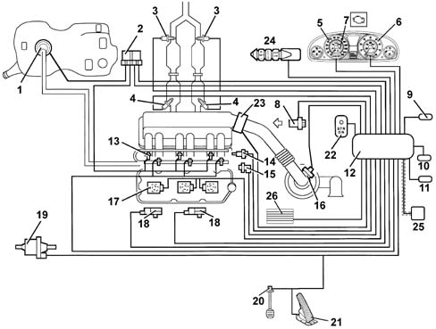
- 1, Fuel pump.
- 2, Relays.
- 3, Lambda sensors downstream of the catalyzer.
- 4, Lambda sensors upstream of the pre-catalyzer.
- 5, Rev counter.
- 6, Speedometer.
- 7, Injection warning light.
- 8, Timing sensor.
- 9, Climate control system connector.
- 10, Tester connector.
- 11, Lancia CODE connector.
- 12, Engine Control Node.
- 13, Injectors.
- 14, Coolant temperature sensor.
- 15, RPM sensor.
- 16, Air flow meter with air temperature sensor.
- 17, Ignition coils.
- 18, Detonation sensors.
- 19, Fuel vapour recirculation solenoid.
- 20, Brake pedal switch.
- 21, Accelerator pedal potetiometer
- 22, Sport throttle response.
- 23, Throttle body built into DVE
- 24, Cruise control.
- 25, CAN line.
- 26, Engine coolant temperature control unit.
DIAGRAM SHOWING INFORMATION ENTERING/LEAVING ENGINE CONTROL NODE.
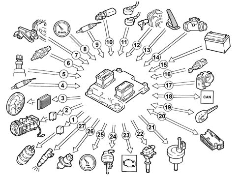
- 1, Fuel pump.
- 2, Air conditioner compressor.
- 3, Electric fan.
- 4, Lambda sensors upstream of the pre-catalyzers.
- 5, Cruise control.
- 6, Quadrinary.
- 7, Brake - clutch pedal switch.
- 8, Timing sensor.
- 9, Speedometer.
- 10, Lambda sensors downstream of the catalyzers.
- 11, Coolant temperature sensor.
- 12 Knock sensors.
- 13, RPM sensor.
- 14, Accelerator pedal potetiometer.
- 15, Air flow meter with air temperature sensor.
- 16, Battery.
- 17, Throttle body built into DVL
- 18, CAN line (for communication With ABS/ASR and automatic transmission control units).
- 19, Lancia CODE.
- 20, Diagnostic tester input
- 21, Fuel vapour recirculation solenoid.
- 22, Ignition coils.
- 23, Injection warning light.
- 24, Rev counter.
- 25, Injectors.
OPERATION
Operating strategies
Injection system
The essential conditions to be met by the air-fuel mixture for efficient operation of engines with controlled ignition systems are mainly as follows:
- the metering (air/fuel ratio) must be kept as close as possible to stoichiometric levels to assure maximum catalytic converter conversion capacity (max. efficiency).
- homogeneity of the mixture, consisting of petrol distributed throughout the air as finely and uniformly as possible.
Information that the Engine Control Node processes to control optimum metering is received by electrical signals emitted by:
- air flow meter (debimeter) and air temperature sensor, for the exact quantity of air taken in.
- rpm sensor that generates an alternating single-phase signal whose frequency is an indicator of engine rpm. The Engine Control Node uses this signal to detect MISFIRE.
- throttle potentiometer, to detect the required acceleration conditions.
- coolant temperature sensor on the thermostat.
- lambda sensors to measure exhaust gas oxygen content.
Two lambda sensors are located on the exhaust system (one per block) at the preconverter input. Two further lambda sensors are also fitted downstream of the converters to determine converter efficiency and correct injection times for both blocks in time to ensure maximum cat conversion efficiency at all times.
Ignition system
The ignition system is static, inductive discharge type (i.e. without a HT distributor) with power modules located inside the Engine Control Node.
The ignition system is arranged so that each coil supplies the spark plugs of the associated cylinder.
The advantages of this solution are:
- lower electrical overload;
- guaranteed constant discharge on each spark plug.
The Engine Control Node contains a memory map with a set of optimum ignition advance values (for the cylinder in combustion phase) that the engine can adopt according to the required speed and engine load.
The Engine Control Node corrects the advance value mainly on the basis of:
- engine coolant temperature:
- intake air temperature.
- knock.
Information that the Engine Control Node processes to control the coils is received by electrical signals emitted by:
- air flow meter (debimeter) and air temperature sensor, for the exact quantity of air taken in.
- rpm sensor that generates an alternating single-phase signal whose frequency is an indicator of engine rpm.
- knock sensor (on the upper part of the crankcase between the two heads) to recognise the cylinder with knock and thus correct the ignition advance.
- throtle position potentiometer to recognise minimum, partial and full-gas load conditions.
- timing sensor.
The Engine Control Node uses the rpm signal to recognise misfiring that could damage the catalytic converters.
Self-learning
The Engine Control Node runs its initialisation program under the following conditions:
Engine Control Node removal/refitting or replacement.
removal-refitting or replacement of the throttle body built into the DVE.
removal-refitting or replacement of the rpm sensor/phonic wheel for detection of misfiring.
The values stored by the Engine Control Node are maintained when the battery is disconnected.
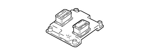
System self-adjustment
The Engine Control Node is equipped with a self-adjustment function that is designed to recognize the changes that take place in the engine due to the processes of bedding in and ageing of both the components and the engine itself in time.
These changes are memorized in the form of modifications to the basic map and are designed to adapt the operation of the system to the gradual alterations in the engine and the components compared with when they were new.
This self-adjustment function also makes it possible to compensate for the inevitable differences in any replacement components (due to production tolerances).
The Engine Control Node modifies the basic map in relation to engine specifications when new on the basis of an exhaust gas analysis.
The self-adjustment parameters are not deleted if the battery is disconnected.
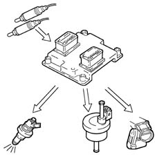
Self-diagnosis
The control unit self-diagnostic system checks that the system is working properly and indicates any irregularities by means of an MIL warning light in the instrument panel with a standardized ideogram and colour laid down by European regulations. This warning light indicates engine management faults and also faults detected by EOBD diagnostic strategies.
The MIL warning light operating (mil) strategy is as follows:
- with the ignition on, the warning light comes on and remains on until the engine has been started up. The control unit self-diagnostic system checks the signals coming from the sensors comparing them with the permitted limits.
Fault indication during start up:
- failure of the warning light to go out when the engine has been started indicates that there is an error memorized in the control unit.
Fault indication during operation:
- the warning light comes on in flashing mode to indicate possible catalytic converter damage due to misfiring.
- the warning light comes on in constant mode to indicate the presence of engine management or EOBD diagnostic errors.
RECOVERY
From time to time the Engine Control Node defines the type of recovery according to the components that are faulty. The recovery parameters are managed by components that are not faulty.
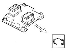
Lancia CODE recognition
When the Body Computer receives an ignition ON signal, it communicates wtih the Engine Control Node to allow start-up. For vehicles with Passive Entry, see [DF55].
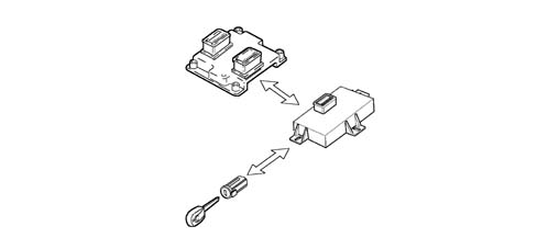
Cold starting check
Under cold starting conditions, the mixture naturally becomes leaner and this gives rise to low fuel evaporation at low temperatures:
- fuel condensation on inner walls of the intake manifold.
- higher lubrication oil viscosity.
The Engine Control Node detects this condition and corrects injection time on the basis of:
- coolant temperature.
- intake air temperature.
- battery voltage.
- engine rpm.
The ignition advance is determined solely on the basis of rpm and coolant temperature.
During the start-up stage, the Engine Control Node sends an initial simultaneous injection command to all injectors (full-group injection). Once cylinder phase has been detected, normal phased sequential operation can begin.
While the engine is warming up, the Engine Control Node controls the throttle body built into the DVL to modulate the amount of air required to ensure engine revs are high enough to keep the engine running.
RPM is made to decrease with increasing temperature until the rated level is reached with the engine warm.
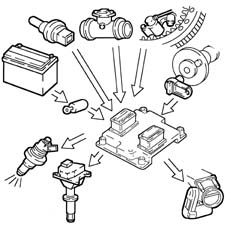
Combustion - Lambda sensor check
In EOBD systems, the lambda sensors are all the same type and located upstream of the catalytic conversion system and downstream of the converter. The upstream sensors determine concentration control known as the 1st loop (upstream sensor closed loop). The sensors downstream of the catalytic converter are used to for converter diagnostics and to fine-tune 1st loop control parameters. The second loop is therefore adaptive to make up for production discrepancies and slight drift that upstream sensor responses could experience due to ageing and contamination. This control is known as 2nd loop control (downstream sensor closed loop).
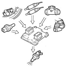
Knock control
The Engine Control Node may delay ignition selectively for a particular cylinder on the basis of a combination of parameters received from knock and timing sensors and:
- reduce ignition advance in 3° steps to a maximum of 9°.
- update the threshold to take into account underlying noise levels and engine ageing.
During acceleration, the Engine Control Node uses a higher threshold due to the higher engine noise.
When the knock disappears, the Engine Control Node increases ignition advance in 0.75° steps until recovery is complete.
The Engine Management Node self-adaptive function:
- stores advance reductions that are repeated continuously.
- adjusts mapping to the various different engine service conditions.
Recovery:
- if the timing sensor or knock sensor or Engine Control Node should fail, a variable ignition delay is implemented on the basis of rpm and engine temperature. Maximum ignition delay is always less than 9° engine.
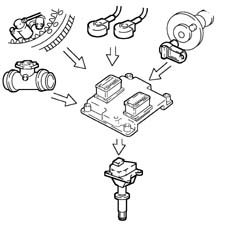
Check on enrichment during acceleration.
In cases of high acceleration demand, the Engine Control Node modifies injection time and throttle position.
Recovery:
- The Engine Control Node replaces the signal from the faulty air flow meter with a signal from the potentiometer built into the throttle body integral with the DVL.
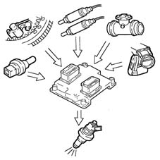
Fuel cut off during over-run (cut-off)
The Engine Control Node under the following circumstances:
- detection of idling status.
- rpm above a certain threshold.
deactivates fuel injection on the basis of:
- rpm.
- engine temperature.
- Vehicle speed.
Before reaching idling level, the rpm descent rate is assessed.
If this exceeds a certain level, fuel injection is partially re-activated to ensure that engine rpm drops smoothly to idling level.
Once idling speed has been achieved, normal functions are resumed.
Fuel cut-off is active only 20 seconds after engine start-up.
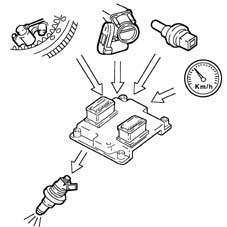
Fuel vapour recovery.
Fuel vapours (pollutants) collected in the activated carbon filter (canister) are directed to the intake ports to be burnt.
This is mediated by a solenoid controlled by the Engine Control Node that holds the solenoid closed for 60 seconds after start-up and then opens it for 90 seconds.
During this time period (90 seconds), the lambda sensor monitors combustion and the Engine Control Node compares levels with the basic map.
If no changes are detected, the Engine Control Node closes the solenoid. Otherwise it keeps it open for a further 90 seconds to flush the canister.
Filter flushing flow is limited to a small percentage of the air flow read by the debimeter to ensure driveability and engine emission settings are affected as little as possible.
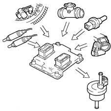
Maximum rpm check.
According to the rpm level reached by the engine, the Engine Control Node:
- above 6800 rpm, cuts off the fuel supply to the injectors (rpm can rise to a peak of 7000 rpm for a period no longer than 5 secs.).
- below 6600 rpm, injector control is resumed.
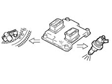
Fuel pump control
Engine Management Node:
- supplies the fuel pump.
- key ON (for 5 secs).
- key on START-UP and revs %lt; 25 rpm.
- cuts off fuel supply to pump.
- key in OFF position.
- with revs %lt; 25 rpm.
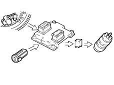
Connection with climate control system.
The compressor takes up power from the engine when the climate control system is activated.
When idling, the Engine Control Node adjusts air flow to the new power requirement. This offers the benefit of maintaining optimum driveability.
The Engine Control Node manages compressor cut-out.
- over 6500 rpm.
- above a set engine coolant temperature threshold (117°C);
- upon start-up.
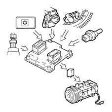
Recognition of cylinder position
During each engine revolution, the Engine Control Node detects the cylinder in combustion phase:
- controls the injection and ignition sequence for the appropriate cylinder.
When the timing sensor is faulty, the Engine Control Node cannot detect whether cylinder no. 1 or cylinder no. 5 is in combustion phase and implements the following strategies:
- with the engine running, it ensures the engine runs correctly due to its memorised cylinder sequence.
- if the engine is turned off and restarted, the ignition is activated for coil pairs with a lost spark. Knock control is deactivated and a fixed delay is applied for all cylinders.
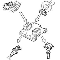
Check on optimum injection time for each cylinder
The Engine Control Node computes the optimum injection time for each cylinder on the basis of special maps:
- it modifies the injection opening start point.
- it maintains the closure point determined by the mapping, selected on the basis of rpm.
- fuel injection is sequential and phased for each cylinder (SEFI).
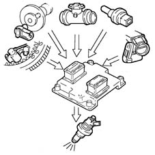
Ignition advance adjustment.
The Engine Control Node processes signals from the sensors and determines:
- injection advance for each cylinder
- ignition delay for the relevant cylinder (affected by knock).
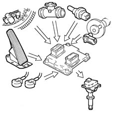
Idle speed check.
The Engine Control Node detects idling status when the accelerator pedal is released.
The Engine Control Node controls idle speed on the basis of appliances activated and brake-clutch pedal signals and governs motorised throttle postion.
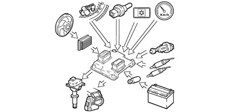
Fan control
The Engine Control Node controls fan activation on the basis of coolant temperature:
- 1st speed activation temperature 95°C.
- 2nd speed activation temperature 102°C.
If the air conditioning system is turned on, the Engine Control Node controls fan 1st speed activation.
When no coolant temperature signal is present, the Engine Control Node implements the recovery function by activating the fan at the 2nd speed until the error is removed.
When the fan is deactivated, the throttle opening is increased to prevent engine rpm from falling.
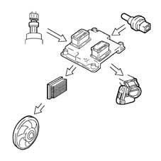
Cruise control system check (where fitted).
The Engine Control Node governs the motorised throttle directly according to cruise control lever position to modulate and maintain a stored vehicle speed.
A warning light on the dashboard activated by the Engine Control Node indicates system operation or deactivation status.
Cruise control is temporarily disabled:
- by operating the brake,
- by operating the clutch;
the recall button returns to the stored speed.
Cruise control is not disabled when the accelerator is pressed (e.g. to overtake) and automatically restores the vehicle to the set speed as soon as the accelerator is released.
The ASR function (antispin) takes precedence over cruise control for safety reasons.
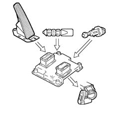
Connection with ABS/ASR control unit (where fitted).
Communication between the Engine Control Node and the ABS/ASR control unit is via the CAN line available on both control units.
If the wheels slip (indicated by the ABS/ASR control unit), the Engine Control Node reduces drive torque by:
- reducing ignition advance.
- reducing throttle opening angle.
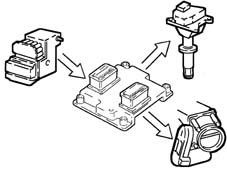
Connection with automatic transmission control unit (where fitted).
Communication between the Engine Control Node and the CAE control unit is via the CAN line available on both control units.
If the wheels slip (indicated by the CAE control unit), the Engine Control Node reduces drive torque by:
- reducing ignition advance.
- reducing throttle opening angle.
Recovery: when the CAN line is faulty, the Engine Control Node identifies speed selector position (D-P-N) by means of a signal from a switch on the selector. If the lever is in D position, the Engine Control Node reduces torque.
The CAE control unit implements its own specific recovery strategy.
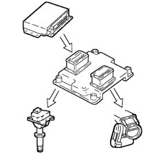
DESCRIPTION OF COMPONENTS
Engine Management Node
Specifications
The Engine Control Node is fitted in the engine bay on the intake chamber.
The Engine Control Node memory is flash eprom type, i.e. it can be overwritten externally without having to adjust the hardware.
Replacement of the Engine Control Node or integrated throttle body requires the initialisation procedure to be run.
Pin out
The Engine Control Node pin-out for connector A is as follows:
- A1, Cruise Control warning light.
- A2, Fuel vapour solenoid control.
- A3, Lancia CODE connection.
- A4, Not connected.
- A5, Speed selector (solo a.t.).
- A6, Compressor activation request.
- A7, Accelerator pedal potentiometer supply.
- A8, Potentiometer signal - 1 accelerator pedal.
- A9, Quadrinary - fan 1st speed request.
- A10, Cruise Control ON/OFF.
- A11, Automatic transmission version coding.
- A12, Linea CAN-L.
- A13, Compressor relay control.
- A14, Not connected.
- A15, Direct power supply.
- A16, Ignition-operated power supply, via main relay.
- A17, Not connected.
- A18, Cruise Control warning light.
- A19, Excess coolant temperature warning light.
- A20, Provision for "Flash programming".
- A21, Not connected.
- A22, Fuel level sensor.
- A23, Not connected.
- A24, Potentiometer earth - 1 accelerator pedal.
- A25, Potentiometer earth -2 accelerator pedal.
- A26, Brake light switch
- A27, Brake light switch.
- A28, SPORT function switch.
- A29, CAN-H line.
- A30, Fuel pump relay control.
- A31, Main relay activation.
- A32, Ignition-operated power supply, via main relay.
- A33, Not connected.
- A34, SPORT function warning light.
- A35, Rev counter signal.
- A36, Not connected.
- A37, Not connected.
- A38, Signal from air conditioner.
- A39, Not connected.
- A40, Potentiometer signal -2 accelerator pedal.
- A41, Quadrinary - fan 2nd speed request.
- A42, Cruise Control Resume.
- A43, Cruise Control SET +.
- A44, Speedometer sensor signal.
- A45, CAN-H line
- A46, Injection warning light.
- A47, Ignition-operated power supply.
- A48, Ignition-operated power supply, via main relay.
- A49, Not connected.
- A50, 1st speed fan control.
- A51, Not connected.
- A52, Fuel consumption signal.
- A53, Diagnostics connector (K line).
- A54, Air temperature sensor signal.
- A55, Not connected
- A56, Power supply for accelerator pedal potentiometer.
- A57, Air flow meter signal.
- A58, Cruise Control SET -.
- A59, Clutch pedal switch.
- A60, Oil pressure switch.
- A61, CAN-L line.
- A62, Fan 2nd speed control.
- A63, Power supply for debimeter.
- A64, Not connected.
The Engine Control Node pin-out for connector B is as follows:
- B1, Throttle body motor earth.
- B2, Lambda sensor heating (pre-cat. 2) (front block).
- B3, Cylinder injector control 2.
- B4, Not connected.
- B5, Not connected.
- B6, Reference earth for knock sensor 2.
- B7, Lambda sensor earth (pre-cat 2).
- B8, Not connected.
- B9, Not connected.
- B10, Engine rpm sensor.
- B11, Not connected.
- B12, Lambda sensor heating (post-cat. 2).
- B13, Not connected.
- B14, Cylinder 3 coil control.
- B15, Cylinder 2 coil control.
- B16, Cylinder 1 coil control.
- B17, Throttle body motor power supply.
- B18, Lambda sensor heating (post-cat. 2).
- B19, Cylinder injector control 1.
- B20, Cylinder injector control 3.
- B21, Not connected.
- B22, Knock sensor 1.
- B23, Lambda sensor signal (pre-cat. 1) (rear block).
- B24, Potenziometer 1 throttle body.
- B25, Engine coolant temperature.
- B26, Sensor reference earth.
- B27, Not connected.
- B28, Lambda sensor signal (post-cat. 1).
- B29, Not connected.
- B30, Cylinder 6 coil control.
- B31, Cylinder 5 coil control.
- B32, Cylinder 4 coil control.
- B33, Throttle body motor earth.
- B34, Lambda sensor heating (pre-cat. 1).
- B35, Cylinder injector control 4.
- B36, Cylinder injector control 6.
- B37, EGR solenoid control (provision).
- B38, Knock sensor 2.
- B39, Lambda sensor signal (pre-cat. 2) (front block).
- B40, Potenziometer 2 throttle body.
- B41, Not connected.
- B42, Timing sensor signal.
- B43, Not connected.
- B44, Lambda sensor signal (post-cat. 2).
- B45, Not connected.
- B46, Not connected.
- B47, Not connected.
- B48, Not connected.
- B49, Throttle body motor power supply.
- B50, Lambda sensor heating (post-cat. 1).
- B51, Timing reference earth.
- B52, Cylinder injector control 5.
- B53, Not connected.
- B54, Reference earth for knock sensor 1.
- B55, Lambda sensor earth (pre-cat. 1).
- B56, Not connected.
- B57, Not connected.
- B58, Throttle body motor potentiometer power supply.
- B59, Engine rpm sensor.
- B60, Lambda sensor heating (post-cat. 1).
- B61, Not connected
- B62, Not connected.
- B63, Not connected.
- B64, Not connected.
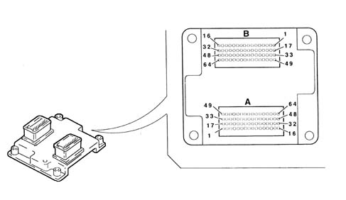
Injectors
Specifications
The single-jet injectors are installed on the distribution manifold and held by the manifold into their seats on the intake ducts.
A safety detent secures the injectors to the manifold and two o-rings assures a seal.
The injectors are responsible for delivering the required amount of fue to the engine.
They are "all or nothing" devices because they can exist in only two stable states, i.e. open or closed. They allow fuel through when open and prevent it from passing when they are closed.
They essentially consist of a nozzle controlled by an electromagnet and a return spring (4).
In rest position, pin (2) integral with core (3) is pressed by the spring against the end of injector nose (6) to close the hole and ensure a seal to prevent fuel emergence when not required.
As soon as coil (5) is excited, the core is attracted and compresses the spring by opening the nozzle hole and allowing fuel to emerge.
Assuming the physical properties of fuel (viscosity (*), density) and the pressure increase (via the pressure regulator) to be constant, the amount of fuel injected depends solely on injector opening time.
Winding excitation time is normally indicated as "excitation time".
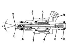
- 1 Injector body.
- 2 Pintle.
- 3 Magnetic core.
- 4 Coil spring.
- 5 Winding.
- 6 Injector nose.
- 7 Adjustable thrust spring.
- 8 Filter.
- 9 Electrical connection.
- 10 Sealing ring.
Engine coolant temperature sensor
Specifications
This is fitted on the thermostatic cup and measures coolant temperature by means of a dual NTC thermistor with negative resistance coefficient.
An NTC thermistor sends a signal to the Engine Control Node while the node sends a signal to the control panel gauge and warning light.
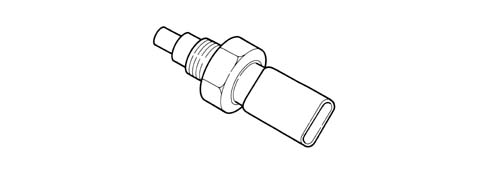
The sensor is designed using semiconductor technology. In other words, the resistance level drops if sensor element temperature increases with increasing coolant temperature.
Because the resistance does not change in linear fashion as temperature increases, it is relatively higher at low temperatures than at high temperatures.
Detonation sensors
Specifications
The piezoresistive knock sensors are fitted on the crankcase between the two heads. They measure the intensity of vibrations caused by knock in the combustion chambers.
The piezoresistant crystal in the sensor detects vibrations generated at frequencies between 12 and 16 Hz and converts them to electrical signals that are sent to the Engine Control Node.
The knock sensor bolt tightening torque is 1.95 -2.05 daNm.

Operation
The molecules of a quartz crystal are electrically polarised.
In rest condition (A), the molecules do not display any particular orientation.
When the crystal is subject to pressure or impact (B), their degree of alignmnent is directly proportional to the pressure acting on the crystal. This orientation generates a voltage at the crystal terminals.
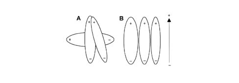
- A, Rest position
- B, Position under pressure.
Rpm sensor
Specifications
This is fitted on the crankcase and faces the phonic wheel on the flywheel.
The sensor is inductive type, i.e. it uses changes in the magnetic field generated by the phonic wheel teeth (60-2 teeth) passing in front of the sensor element.
The Engine Control Node uses the rpm sensor signal to:
- determine speed of rotation.
- determine crankshaft angular position.
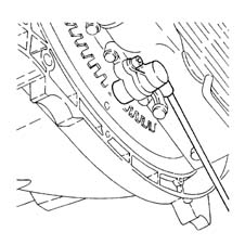
Operation
The changeover from full to empty determined by the presence or absence of a tooth brings about a magnetic flux change sufficient to generate an induced alternating voltage proportional to the number of teeth on a ring (or phonic wheel).
The frequency and amplitude of the voltage send to the Engine Control Node provides the node with an indication of engine angular speed.
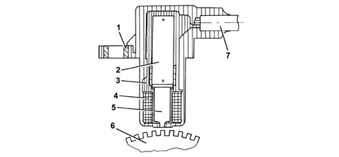
- 1 Brass bush.
- 2 Permanent magnet.
- 3 Plastic sensor casing.
- 4 Winding or coil.
- 5 Polar core.
- 6 Ring gear or flywheel.
- 7 Coaxial paired cable or electrical connection.
The recommended distance (gap) between the end of the sensor and the flywheel for obtaining correct signals should be 0.8 ¸ 1.5 mm.
This distance is not adjustable. If the gap is found to be outside the tolerance limits, check the condition of the sensor and phonic wheel.
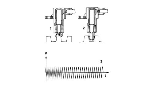
- 1 Maximum magnetic flux.
- 2 Minimum magnetic flux.
- 3 Induced alternating voltage plot.
Timing sensor.
Specifications
This Hall effect sensor is fitted to the right cylinder head and faces a disc on the rear end of the camshaft - head discharge.
A pin on the disc allows the sensor to indicate the engine timing position.
The Engine Control Node uses the timing sensor signal to identify T.D.C. at the end of compression.
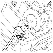
Operation
A current-carrying semiconductor layer immersed in a normal magnetic field (force lines at right angles to current direction) generates a potential difference known as a Hall voltage at its terminals.
During rotation of disc (1), when pin (3) passes over sensor (2), it blocks the magnetic field to generate a low output current.
Conversely, when sensor (2) reads after pin (3), the signal becomes high.
As a result, the high signal alternates with the low signal once every two engine revolutions, i.e. when cylinder no. 1 is 58° before T.D.C.
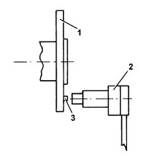
- 1 Camshaft disc.
- 2 Timing sensor.
- 3 Pin.
D.V.E.integrated throttle casing
Specifications
This is fitted on the intake chamber and regulates the amount of air taken in by the engine.
According to the signal received from the accelerator pedal potentiometer, the Engine Control Node controls throttle opening by means of a direct current motor built into the DVE integrated throttle body.
Throttle opening takes place from 0° to 80°, i.e. including idle speed adjustment range.
The DVE integrated throttle body is equipped with two built-in potentiometers, each of which controls the other.
If both potentiometers should fail or in the case of a power cut, the Engine Control Node reduces drive torque on the basis of accelerator pedal position.
- with the pedal fully depressed, it cuts off fuel to one or more pistons until a maximum speed of 2500 rpm is reached;
- with the pedal in intermediate positions, it cuts off fuel to one or more pistons until speed less than 2500 rpm is reached.
Replacement of the DVE integrated throttle body requires the initialisation procedure to be run.
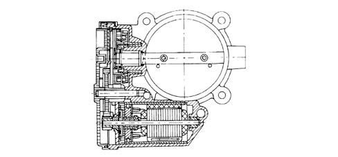
Air flow meter with built in air temperature sensor
Specifications
The debimeter is located on the air intake sleeve and is hot film type.
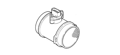
The debimeter contains an integral intake air temperature sensor.
The air flow meter cannot be dismantled.
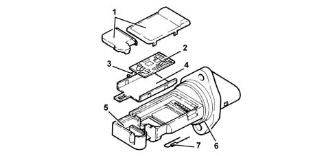
- 1 Covers.
- 2 Electronic card.
- 3 Sensor.
- 4 Mounting plate.
- 5 Mount.
- 6 O - Ring seal
- 7 Temperature sensor.
Operation
The principle of operation is based on a heated membrane positioned within a measurement channel that carries air into the engine.
The hot film membrane is maintained at constant temperature (about 120°C higher than the incoming air temperature) by the heating coil.
The air mass that flows through the measurement channel tends to remove heat from the membrane. Current must therefore flow through the coil to maintain the membrane at a constant temperature.
This current is measured with a suitable Wheatstone bridge.
The current is thus proportional to the air flow mass.
The debimeter measures air mass (not volume) directly and thus eliminates problems of temperature, altitude, pressure etc.
Specifications
Rated flow (with voltage 4.56 V): 640 kg/h
Rated resistance at 25ºC: 2.0 kOhm ± 5%
Accelerator pedal potentiometer
Specifications
The accelerator pedal consists of two integral potentiometers, a main one and a safety one.
The Engine Control Node implements the following recovery strategies.
- if one of the two potentiometers fails, this allows the throttle to be opened to a maximum of 40° over a long time period;
- if both potentiometers fail completely, it prevents throttle opening.
Composition
The sensor consists of a case secured to the pedal unit by a flange. This contains an axially-located shaft connected to a dual-track potetiometer.
A coil spring on the shaft ensures the correct amount of resistance to pressure while a second spring ensures return following release.
Operating field from 0° to 70°; mechanical stop at 88°.
If one or both potentiometers fail, the whole accelerator pedal must be replaced because it cannot be dismantled.
Parts & tools for this job Staging For 2002 Lancia Thesis
- PARTFuel filterSearch: Lancia Thesis 2002 fuel filter
- TOOLFuel pressure test kitSearch: fuel pressure test kit
- TOOLFuel line disconnect toolSearch: fuel line disconnect tool
Links open Amazon search results in a new tab. As an Amazon Associate I earn from qualifying purchases.