
Emission control system: Specifications
- Make
- Lancia
- Model
- Thesis Factory Service Manual
- Year
- 2002–2009
- Section
- Emission control system › Specifications
Specifications
FUNCTION.
During engine operation, oil vapour from the crankcase collects in the cylinder head.
A proportion of the oil vapour condenses and falls into the crankcase. The remaining vapour is directed to the intake through pipes (1) and (2).
When the engine is idling, oil vapours flow to the intake through pipe (1). At higher loads, they flow through pipe (2).
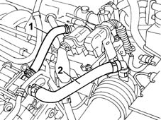
FUNCTION
Vapours from the fuel tank are directed through two float valves (1) to separator (2).
Vapours condense in the separator and fall into the tank.
Uncondensed vapours are directed to canister (4) through multifunction valve (3) and a special pipe. They are then absorbed and stored in the activated carbon inside the canister.
The vapours flow to the intake manifold through solenoid (5) controlled by the injection-ignition control unit.
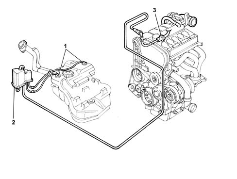
- 1 Float valves.
- 2 Fuel vapour separator.
- 3 multifunction valve.
- 4 Fuel vapour filter (canister).
- 5 Fuel vapour solenoid.
FUNCTION
Vapour from the fuel tank flows through two float valves (1) to separator (2).
Vapours that condense in the separator fall into the tank.
Uncondensed vapours are sent to canister (4) through multifunction valve (3) and a special pipe. Here they are absorbed and stored in by the active carbon inside.
The vapours flow on to the intake manifold through solenoid (5) controlled by the injection-ignition control unit.
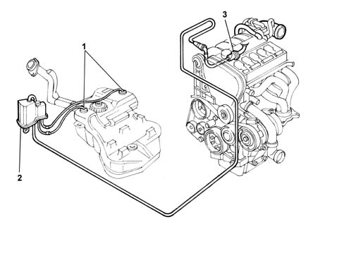
- 1 Float valves
- 2 Fuel vapour separator
- 3 Multifunction valve.
FUNCTION
During engine operation, oil vapour frm the crankcase collect in the cylinder heads.
A portion of the oil vapours condense and fall into the crankcase. The remaining vapours are directed to the intake via pipes (1) and (2).
When idling, oil vapours flow through pipe (1). At higher loads, they flow through pipe (2).
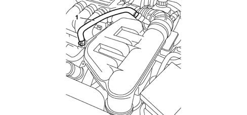
FUNCTION
Vapours from the tank flow through two multifunction valves and are directed to the separator.
The vapours condense in the separator and drop into the tank.
Uncondensed vapours are directed through the pipe to the canister, where they are absorbed and stored by the activated carbon.
The vapours flow to the intake chamber through a solenoid controlled by the injection control unit.
Multifunction valves
Multifunction valve functions are as follows:
- tank pressurisation.
- fastening.
- seal in the case of roll-over.
The multifunction valves are heat-welded to the fuel tank and cannot therefore be replaced individually.
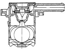
Tank pressurization.
Tank pressure is maintained at 30 - 45 bars using a fluorosilicone rubber valve resting on a sealing edge.
The valve is supported by a stainless steel plate and held in place by a spring.
When tank pressure exceeds a set level, it overcomes spring resistance and allows the valve to rise so that fuel can flow out toward the canister.
The valve re-closes when the pressure returns to within specified limits.
Retainer.
Under specific vehicle operating conditions, a vacuum develops in the tank due to:
- heat fluctuations.
- fuel consumption.
In this case, the valve's function is to restore pressure in the tank by admitting air.
A fault in this function may lead to juddering or stalling because not enough fuel can reach the pump.
This function is performced by the goosebill valve formed directly out of the fluorosilicone seal.
Seal in the case of roll over.
The roll-over function prevents fuel emerging from the tank if the vehicle rolls over or tilts too far to one side.
During normal vehicle operation (cornering, acceleration, braking etc.), the fuel may slop over into the canister.
The high rollover sensitivity prevents this slop-over from occurring.
The roll-over closure angle is 33°.
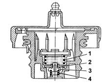
Safety and ventilation valve
This valve is built into the fuel filler cap and performs as follows, depending on fuel pressure in the tank.
Excess pressure in tank.
When tank pressure exceeds the specified value, it acts on plate (2) and overcomes the load on spring (1) so that excess vapours can be vented outside.
Vacuum in reservoir.
When excess pressure builds up in the tank due to fuel consumption, this overcomes the load on spring (4) and moves valve (3) to admit air.
Canister
This is fitted to the right front wheel arch and consists of an activated carbon filter element that absorbs fuel vapours from the separator.
A one-way valve admits outside air (flushing air) during vapour intake.
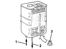
- 1, From multifunction valve.
- 2, To solenoid.
- 3, One-way flushing valve (not on EURO 3 version).
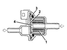
Fuel Vapour Solenoid Valve.
This is fitted on the lower part of the modular intake manifold and is controlled by the injection control unit.
The solenoid allows fuel vapours stored in the canister to flow through to the engine intake.
If deactivated, the solenoid remains in open position. At key-ON, it closes ready for operation.
Electromagnet (1) is excited and attracts plunger (2) that overcomes the load of spring pack (3) to close orifice (4) and prevent fuel vapours from passing through.
Parts & tools for this job Staging For 2002 Lancia Thesis
- PARTExhaust gasketSearch: Lancia Thesis 2002 exhaust gasket
- TOOLPenetrating oilSearch: penetrating oil
- TOOLOBD2 scannerSearch: OBD2 scanner
Links open Amazon search results in a new tab. As an Amazon Associate I earn from qualifying purchases.