
Construction specifications
- Make
- Lancia
- Model
- Thesis Factory Service Manual
- Year
- 2002–2009
- Section
- Emission control system › Construction specifications
CONSTRUCTION SPECIFICATIONS
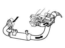
This system makes it possible to send some (5+15%) of the exhaust gases to the intake in certain operating conditions.
This lowers the peak temperature in the combustion chamber restricting the formation of nitrogen oxides (NOx).
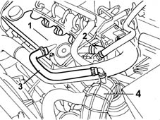
The oil vapour emission control is achieved by means of a separator (1) (a function performed by the tappet cover) which collects the vapours released by the crankcase through the pipe (2).
The temperature difference between the separator and the oil vapours causes partial condensation.
The condensed vapours are sent to the crankcase via the pipe (3).
The vapours that are not condensed are sent, via the pipe (4), to the turbocharger air intake hose.
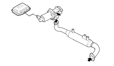
This system makes it possible to send some (5+15%) of the exhaust gases to the intake in certain operating conditions.
This lowers the peak temperature in the combustion chamber restricting the formation of nitrogen oxides (NOx).
The oil vapour emissions are controlled by means of an oil separator (1) which collects the vapours coming from the crankcase (2) and from the tappet cover (3). The condensed vapours return to the sump, via a pipe, whilst the uncondensed vapours are sent, via a pipe (5) to the turbocharger air inlet hose.
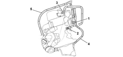
- 1 Oil separator
- 2 Oil vapour outlet from the crankcase
- 3 Oil vapour outlet from the tappet cover
- 4 Condensed vapour sump return
- 5 Inlet vapour delivery pipe
- 6 Regulation valve
There is a regulation valve (6), on the inlet vapour delivery pipe (5), with a spring that in normal conditions acts on a diaphragm keeping it open, thereby allowing the flow of oil vapours coming from the oil separator.
When the vacuum inside the pipe (5) overcomes the calibration of spring, the diaphragm moves thereby closing the duct from the oil vapour separator preventing the intake of oil from the sump.
Parts & tools for this job Staging For 2002 Lancia Thesis
Links open Amazon search results in a new tab. As an Amazon Associate I earn from qualifying purchases.