
Operation
- Make
- Lancia
- Model
- Thesis Factory Service Manual
- Year
- 2002–2009
- Section
- Diesel fuel injection system › Operation
Operation
OPERATING LOGICS
General remarks
The Common Rail system makes it possible to carry out a pre-injection (pilot injection) before T.D.C. with the advantage of reducing the consequences of the pressure in the combustion chamber and reducing the combustion noise typical of direct injection engines.
The Engine Management Node controls the quantity of fuel injected, regulating the line pressure and injection times.
The Engine Management Node processes the following information to control the quantity of fuel to inject:
- engine rpm
- coolant temperature
- supercharging pressure
- air temperature
- intake air quantity
- battery voltage
- diesel pressure
- accelerator pedal position.
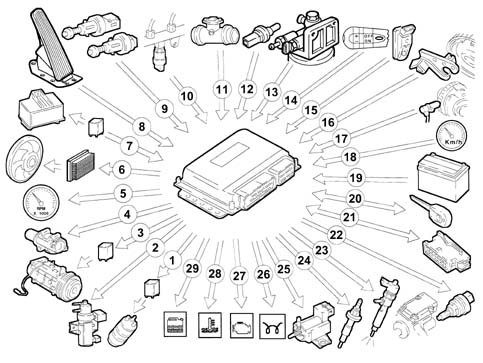
Diagram showing information entering/leaving the Engine Management Node
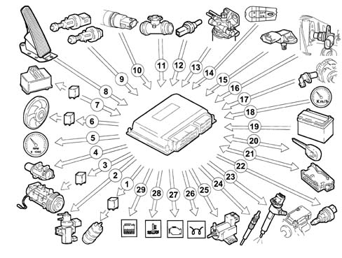
- 1 Auxiliary electric fuel pump
- 2 VGT solenoid valve
- 3 Air conditioning compressor
- 4 E.G.R. solenoid valve
- 5 Rev counter
- 6 Fans
- 7 Heater plugs control unit
- 8 Accelerator pedal potentiometer
- 9 Brake - clutch pedal switch
- 10 Fuel pressure sensor
- 11 Flow meter
- 12 Coolant temperature sensor
- 13 Fuel temperature sensor
- 14 Cruise Control (where fitted)
- 15 Excess pressure sensor
- 16 Timing sensor
- 17 Rpm sensor
- 18 Speedometer
- 19 Battery
- 20 Lancia CODE
- 21 Diagnostic socket
- 22 Pressure regulator
- 23 Injectors
- 24 Heater plugs
- 25 Throttle electro-pneumatic valve
- 26 Heater plugs warning light
- 27 Injection warning light
- 28 Coolant overheating warning light
- 29 Water in the fuel warning light
Self-diagnosis
The control unit self-diagnostic system checks the signals coming from the sensors comparing them with the permitted parameters.
Siganalling of faults during stating
warning light on for 4 seconds indicates test stage
warning light off after 4 seconds indicates no fault with components that can alter values set out by pollution control regulations
warning light on after 4 seconds indicates fault.
Signalling of faults during operation
warning light on indicates fault
warning light off after 4 seconds indicates no fault with components that can alter values set out by pollution control regulations.
Recovery
from time to time the Engine Control Node defines the type of recovery according to the components that are faulty.
the recovery parameters are managed by components that are not faulty.
the warning light flashing indicates that the injectors are not calibrated
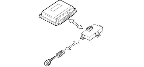
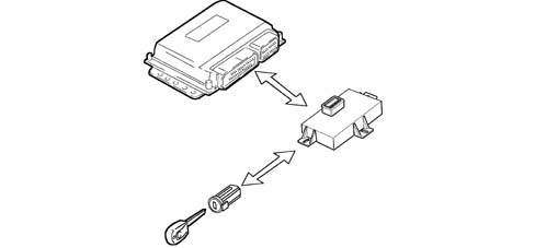
Lancia Code recognition
When the Body Computer receives an ignition ON signal, it communicates wtih the Engine Control Node to allow start-up. For vehicles with Passive Entry
(See group ) 55 ELECTRICAL EQUIPMENT
Fuel temperature control
When the temperature of the fuel, measured by the sensor on the recirculation manifold, is 110°C, the Engine Management Node operates the pressure regulator to reduce the line pressure (it does not alter the injection times).
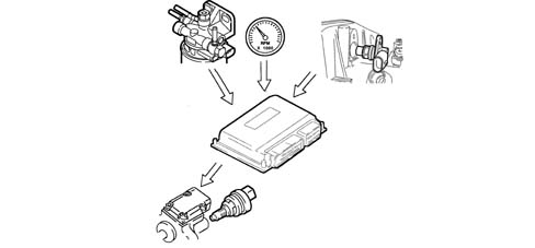
Engine coolant temperature control
When the engine coolant temperature is above 105°C, the Engine Management Node:
- reduces injected fuel quantity (reduces engine power)
- controls the cooling fan via the fan control interface
- switches on the coolant temperature warning light.
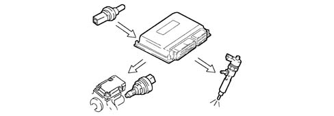
Control of amount of fuel injected
On the basis of the signals coming from the sensors and the values stored, the Engine Management Node:
- controls the pressure regulator
- alters the "pilot" injection time up to 3000 rpm
- alters the "main" injection time.
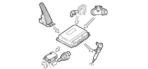
Idle speed check
The Engine Management Node processes the signals coming from the various sensors and regulates the quantity of fuel injected:
- controls the pressure regulator
- alters the injector injection times.
Within certain limits the speed takes the battery voltage into account.
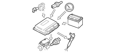
Fuel cut-off during deceleration
During the accelerator pedal release stage, the Engine Management Node implements the following logics:
- cuts off the supply to the injectors
- partly reactivates the supply to the injectors before the idle speed is reached
- controls the fuel pressure regulator.
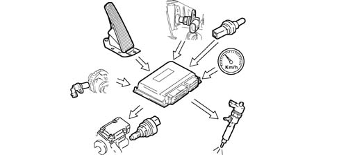
Cylinder balance control up to 3500 rpm
According to the signals received from the sensors, the Engine Management Node controls the torque up to 3500 rpm:
- alters the quantity of fuel injected by the individual injectors (injection time).
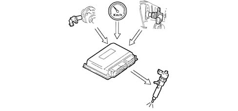
Check on irregular operation
The Engine Management Node processes the signals received from the various sensors and determines the quantity of fuel to inject through:
- the pressure regulator
- the injector opening time.
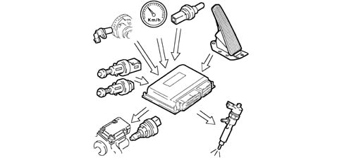
Exhaust fumes control during acceleration
When there is strong acceleration, according to the signals received from the flow meter and the engine rpm sensor, the Engine Management Node determines the optimum amount of fuel to inject:
- controls the pressure regulator
- alters the injector injection times.
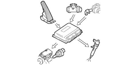
Exhaust gas recirculation control (E.G.R.)
On the basis of the engine load and the signal from the accelerator pedal potentiometer, the Engine Management Node limits the quantity of intake air, implementing the partial intake of exhaust gases, through:
- the adjustment of the opening of the E.G.R. solenoid valve
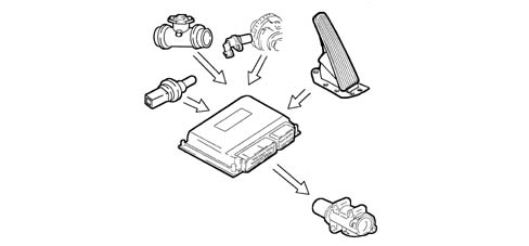
Maximum torque limit control
According to the rpm level, the Engine Control Node calculates the following in pre-defined maps:
- the torque limit
- the permitted fumes (limit).
It compares this minimum values and corrects them with other parameters:
- coolant temperature
- engine rpm
- vehicle speed
- intake air temperature measured by the integrated excess pressure/air temperature sensor
and controls the quantity of fuel to be injected (pressure regulator - injectors).
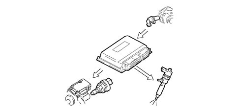
Maximum speed limit control
Depending on the rpm, the Engine Management Node implements two operating strategies:
- at 5000 rpm it cuts off the fuel reducing the line pressure
- beyond 5400 rpm it deactivates the auxiliary pump and the injectors.
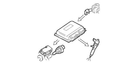
Heater plugs check
During the following stages, the Engine Management Node:
- start-up
- post-starting
applies a timer to the glow plug preheating control unit based on engine temperature.
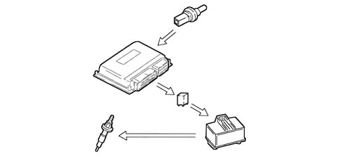
Air conditioning system start of operation check
The Engine Management Node controls the air conditioning compressor:
- switching it on/off when the switch is pressed
- switching it off momentarily (about 6 secs) in the case of strong acceleration or a request for maximum power.
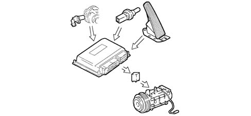
Auxiliary fuel pump check
Irrespective of the engine speed, the Engine Management Node:
- supplies the auxiliary fuel pump with the ignition ON
- cuts off the auxiliary pump supply if the engine is not started within a few seconds.
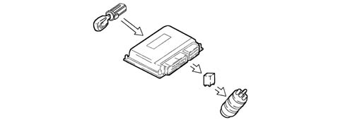
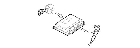
Cylinder position check
During each revolution of the engine the Engine Management Node recognizes which cylinder is in the explosion stroke and controls the injection sequence at the appropriate cylinder.
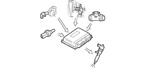
Pilot injection and main injection advance check
According to the signals coming from the various sensors, including the absolute pressure sensor integrated in the Engine Management Node itself, the latter determines the optimum injection point, according to an internal map, based on driving comfort and exhaust emission limits.
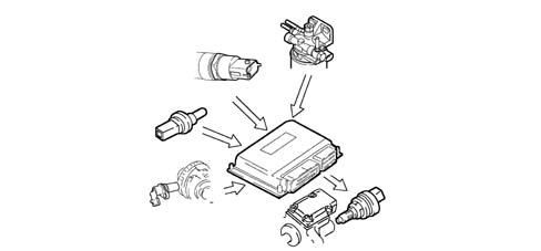
Injection pressure closed cycle check
On the basis of the engine load, determined by processing the signals from the various sensors, the Engine Management Node controls the regulator to produce optimum line pressure.
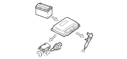
Electrical balance check
According to the battery voltage, the Engine Management Node alters the idle speed:
- increases the injector injection times
- modulates the line pressure.
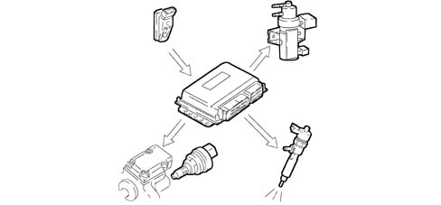
VGT variable geometry turbine operation
The Engine Management Node processes the signal from the supercharging pressure, at the various engine operating speeds and determines the quantity of fuel to inject:
- controls the pressure regulator
- alters the injection time
- regulates the turbine geometry to ensure optimum performance in all operating conditions.
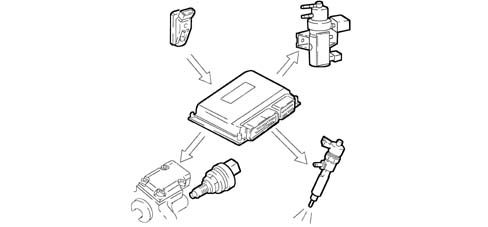
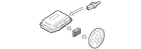
Fan control
According to coolant temperature and coolant pressure in the air conditioning system, the Engine Management Node communicates with the fan control interface to provide enablement for:
- solenoid valve engagement at first or second speeds.
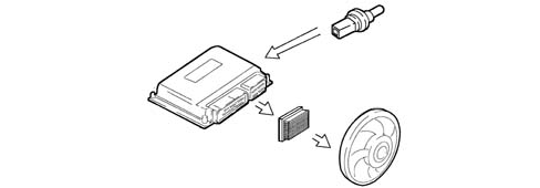
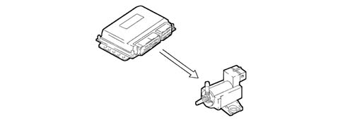
Check on throttle closing when switching off
In order to prevent the engine shuddering when it is switched off, the Engine Management Node controls the immediate closure of the inlet throttle. The throttle remains open in all other operating conditions.
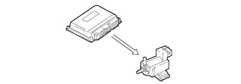
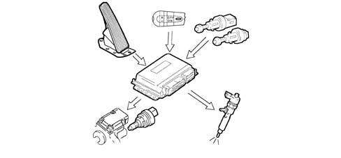
Cruise control system check
Depending on the position of the control lever, the Engine Management Node directly controls the quantity of fuel injected to control and maintain the vehicle speed memorized.
A warning light on the dashboard activated by the Engine Control Node indicates system operation or deactivation status.
Cruise control is temporarily disabled:
- by operating the brake
- by operating the clutch;
the recall button returns to the stored speed.
Cruise control is not disabled when the accelerator is pressed (e.g. to overtake) and automatically restores the vehicle to the set speed as soon as the accelerator is released.
The ASR function (antispin) takes precedence over cruise control for safety reasons.
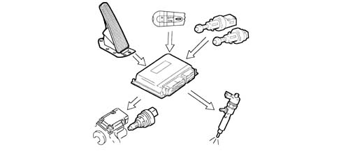
OPERATING LOGICS
General remarks
The Common Rail system makes it possible to carry out a pre-injection (pilot injection) before T.D.C. with the advantage of reducing the consequences of the pressure in the combustion chamber and reducing the combustion noise typical of direct injection engines.
The Engine Management Node controls the quantity of fuel injected, regulating the line pressure and injection times.
The Engine Management Node processes the following information to control the quantity of fuel to inject:
- engine rpm
- coolant temperature
- supercharging pressure
- air temperature
- intake air quantity
- battery voltage
- diesel pressure
- accelerator pedal position.
Diagram showing information entering/leaving the Engine Management Node
- 1 Auxiliary electric fuel pump
- 2 VGT solenoid valve
- 3 Air conditioning compressor
- 4 E.G.R. solenoid valve
- 5 Rev counter
- 6 Fans
- 7 Heater plugs control unit
- 8 Accelerator pedal potentiometer
- 9 Brake - clutch pedal switch
- 10 Fuel pressure sensor
- 11 Flow meter
- 12 Coolant temperature sensor
- 13 Fuel temperature sensor
- 14 Cruise Control (where fitted)
- 15 Excess pressure sensor
- 16 Timing sensor
- 17 Rpm sensor
- 18 Speedometer
- 19 Battery
- 20 Lancia CODE
- 21 Diagnostic socket
- 22 Pressure regulator
- 23 Injectors
- 24 Heater plugs
- 26 Heater plugs warning light
- 27 Injection warning light
- 28 Coolant overheating warning light
- 29 Water in the fuel warning light
Self-diagnosis
The control unit self-diagnostic system checks the signals coming from the sensors comparing them with the permitted parameters.
Siganalling of faults during stating
warning light on for 4 seconds indicates test stage
warning light off after 4 seconds indicates no fault with components that can alter values set out by pollution control regulations
warning light on after 4 seconds indicates fault.
Signalling of faults during operation
warning light on indicates fault
warning light off after 4 seconds indicates no fault with components that can alter values set out by pollution control regulations.
Recovery
from time to time the Engine Control Node defines the type of recovery according to the components that are faulty.
the recovery parameters are managed by components that are not faulty.
Lancia Code recognition
When the Body Computer receives an ignition ON signal, it communicates wtih the Engine Control Node to allow start-up. For vehicles with Passive Entry
(See group ) 55 ELECTRICAL EQUIPMENT
Fuel temperature control
When the temperature of the fuel, measured by the sensor on the recirculation manifold, is 110°C, the Engine Management Node operates the pressure regulator to reduce the line pressure (it does not alter the injection times).
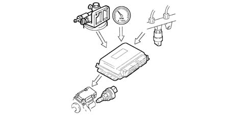
Engine coolant temperature control
When the engine coolant temperature is above 105°C, the Engine Management Node:
- reduces injected fuel quantity (reduces engine power)
- controls the cooling fan via the fan control interface
- switches on the coolant temperature warning light.
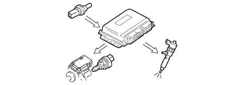
Control of amount of fuel injected
On the basis of the signals coming from the sensors and the values stored, the Engine Management Node:
- controls the pressure regulator
- alters the "pilot" injection time up to 3000 rpm
- alters the "main" injection time.
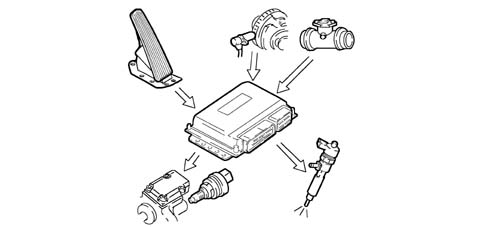
Idle speed check
The Engine Management Node processes the signals coming from the various sensors and regulates the quantity of fuel injected:
- controls the pressure regulator
- alters the injector injection times.
Within certain limits the speed takes the battery voltage into account.
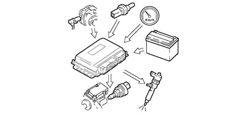
Fuel cut-off during deceleration
During the accelerator pedal release stage, the Engine Management Node implements the following logics:
- cuts off the supply to the injectors
- partly reactivates the supply to the injectors before the idle speed is reached
- controls the fuel pressure regulator.
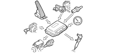
According to the signals received from the sensors, the Engine Management Node controls the idle speed torque:
- alters the quantity of fuel injected by the individual injectors (injection time).
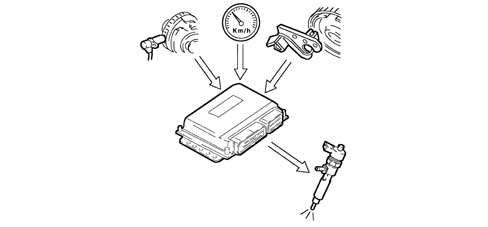
Check on irregular operation
The Engine Management Node processes the signals received from the various sensors and determines the quantity of fuel to inject through:
- the pressure regulator
- the injector opening time.
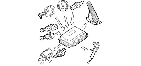
Exhaust fumes control during acceleration
When there is strong acceleration, according to the signals received from the flow meter and the engine rpm sensor, the Engine Management Node determines the optimum amount of fuel to inject:
- controls the pressure regulator
- alters the injector injection times.
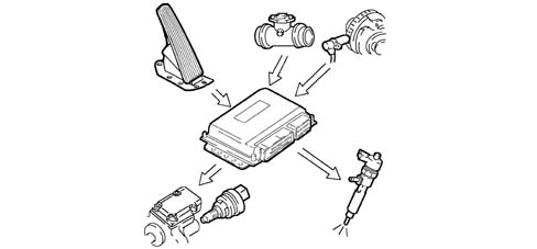
Exhaust gas recirculation control (E.G.R.)
On the basis of the engine load and the signal from the accelerator pedal potentiometer, the Engine Management Node limits the quantity of intake air, implementing the partial intake of exhaust gases, through:
- the adjustment of the opening of the E.G.R. solenoid valve
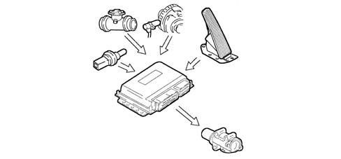
Maximum torque limit control
According to the rpm level, the Engine Control Node calculates the following in pre-defined maps:
- the torque limit
- the permitted fumes (limit).
It compares this minimum values and corrects them with other parameters:
- coolant temperature
- engine rpm
- vehicle speed
and controls the quantity of fuel to be injected (pressure regulator - injectors).
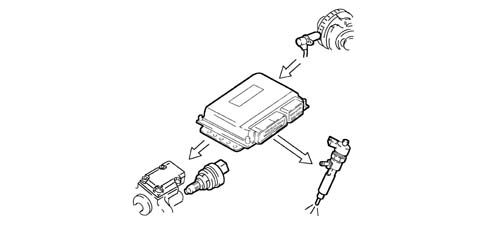
Maximum speed limit control
Depending on the rpm, the Engine Management Node implements two operating strategies:
- at 5000 rpm it cuts off the fuel reducing the line pressure
- beyond 5400 rpm it deactivates the auxiliary pump and the injectors.
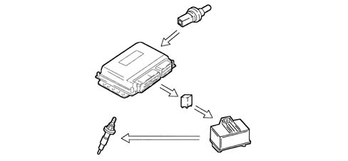
Heater plugs check
- start-up
- post-starting
applies a timer to the glow plug preheating control unit based on engine temperature.
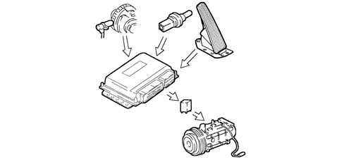
Air conditioning system start of operation check
The Engine Management Node controls the air conditioning compressor:
- switching it on/off when the switch is pressed
- switching it off momentarily (about 6 secs) in the case of strong acceleration or a request for maximum power.
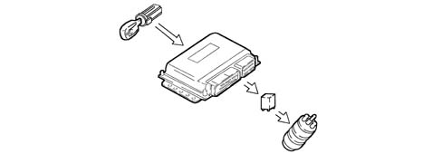
Auxiliary fuel pump check
Irrespective of the engine speed, the Engine Management Node:
- supplies the auxiliary fuel pump with the ignition ON
- cuts off the auxiliary pump supply if the engine is not started within a few seconds.
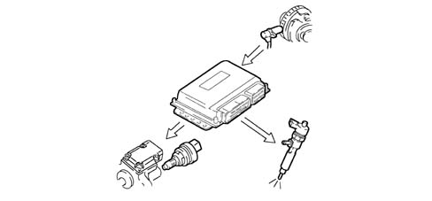
Cylinder position check
During each revolution of the engine the Engine Management Node recognizes which cylinder is in the explosion stroke and controls the injection sequence at the appropriate cylinder.
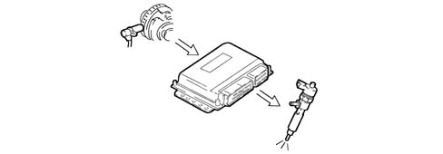
Main injection advance and operation check
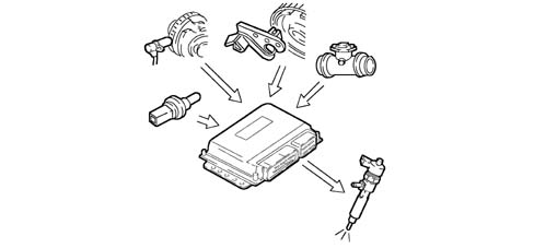
Injection pressure closed cycle check
On the basis of the engine load, determined by processing the signals from the various sensors, the Engine Management Node controls the regulator to produce optimum line pressure.
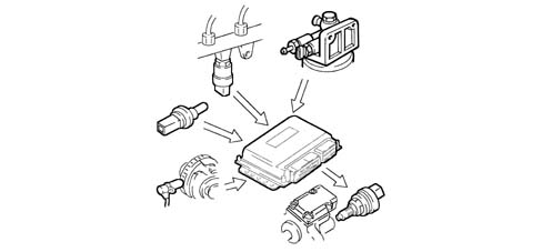
Electrical balance check
According to the battery voltage, the Engine Management Node alters the idle speed:
- increases the injector injection times
- modulates the line pressure.
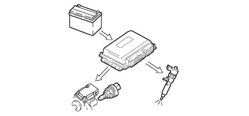
The Engine Management Node processes the signal from the supercharging pressure, at the various engine operating speeds and determines the quantity of fuel to inject:
- controls the pressure regulator
- alters the injection time
- regulates the turbine geometry to ensure optimum performance in all operating conditions.
Fan control
According to coolant temperature and coolant pressure in the air conditioning system, the Engine Management Node communicates with the fan control interface to provide enablement for:
- solenoid valve engagement at first or second speeds.
Check on throttle closing when switching off
In order to prevent the engine shuddering when it is switched off, the Engine Management Node controls the immediate closure of the inlet throttle. The throttle remains open in all other operating conditions.
Cruise control system check
Depending on the position of the control lever, the Engine Management Node directly controls the quantity of fuel injected to control and maintain the vehicle speed memorized.
A warning light on the dashboard activated by the Engine Control Node indicates system operation or deactivation status.
Cruise control is temporarily disabled:
- by operating the brake
- by operating the clutch;
the recall button returns to the stored speed.
Cruise control is not disabled when the accelerator is pressed (e.g. to overtake) and automatically restores the vehicle to the set speed as soon as the accelerator is released.
The ASR function (antispin) takes precedence over cruise control for safety reasons.
Parts & tools for this job Staging For 2002 Lancia Thesis
- PARTGlow plugsSearch: Lancia Thesis 2002 glow plugs
- TOOLGlow plug socketSearch: glow plug socket
- TOOLDiesel compression testerSearch: diesel compression tester
Links open Amazon search results in a new tab. As an Amazon Associate I earn from qualifying purchases.