
Roof node (nim)
- Make
- Lancia
- Model
- Thesis Factory Service Manual
- Year
- 2002–2009
- Section
- Instrument/gauge electrical circuits › Roof node (nim)
Electrical equipmentRoof node (nim)
ROOF NODE (NIM)
SPECIFICATIONS
The Roof Node is an electronic and electro-mechanical control unit that integrates the functions located in the interior mirror and the courtesy light
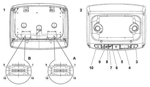
- 1 Rear view
- 2 Front view
- 3 Button for left spot light
- 4 Microphone covers
- 5 Button for courtesy light
- 6 Function warning light (LED)
- 7 Button for anti-theft device (vehicle tilt prevention)
- 8 Function warning light (LED)
- 9 Button for anti-theft device (volumetric sensors inhibition)
- 10 Button for right spot light
OPERATION
The Roof Node carries out the following functions:
- Activation of side lights and dipped headlamps by dusk sensor [F044]
- Management of courtesy lights and front and rear spot lights [F078]
- US volumetric protection of passenger compartment (which can be excluded) [F080]
- Rain sensor acquisition [F114]
- Electro-chromic interior mirror [F128]
- Management of gear lever and rear armrest lighting [F220]
- Activation of alarm by tilt sensor [F233]
In addition it:
- receives and transmits information on the B-CAN line (e.g.: diagnosis, warnings, commands, data)
- integrates the volumetric/tilt sensors
- integrates the courtesy light controls (unstable type)
- integrates the hands-free telephone microphone
- connects with the rear wiring and the wiring at the interior rear view mirror
Connector A PIN OUT
| PIN | FUNCTION |
|---|---|
| 1 | Earth |
| 2 | Electro-chromic exterior mirrors - Positive |
| 3 | Electro-chromic exterior mirrors - Negative |
| 4 | A-bus serial line |
| 5 | Not connected |
| 6 | Not connected |
| 7 | B - CAN A |
| 8 | Not connected |
| 9 | Microphone output (ref) to NIT |
| 10 | +30 from F-39 CPL |
| 11 | Not connected |
| 12 | Not connected |
| 13 | Not connected |
| 14 | Not connected |
| 15 | Negative signal controlling night panel function LED in centre rear courtesy light |
| 16 | B - CAN B |
| 17 | Not connected |
| 18 | Microphone output to NIT |
Connector B PIN OUT
| PIN | FUNCTION |
|---|---|
| 1 | Not connected |
| 2 | A-bus serial line to rain/dusk sensor |
| 3 | Not connected |
| 4 | Electro-chromic exterior mirrors - Negative |
| 5 | Electro-chromic exterior mirrors - Positive |
| 6 | Not connected |
| 7 | Not connected |
| 8 | Rain/dusk sensor (negative) |
| 9 | Electro-chromic interior rear view mirror (negative) |
| 10 | Not connected |
| 11 | Not connected |
| 12 | Rain/dusk sensor (positive) |
| 13 | Electro-chromic interior rear view mirror (positive) |
| 14 | Not connected |
| 15 | Not connected |
| 16 | Electro-chromic interior rear view mirror (reversing signal) |
| 17 | Not connected |
| 18 | Not connected |
Parts & tools for this job Staging For 2002 Lancia Thesis
- TOOLDigital multimeterSearch: automotive digital multimeter
- PARTAssorted fuse kitSearch: car fuse assortment kit
- TOOLWire crimper and connector kitSearch: wire crimper connector kit
Links open Amazon search results in a new tab. As an Amazon Associate I earn from qualifying purchases.