
Fuel tank - r + r and decant fuel
- Make
- Alfa Romeo
- Model
- GT Factory Service Manual
- Year
- 2003–2010
- Section
- Fuel tank and pipes › Fuel tank - r + r and decant fuel
FUEL TANK - R + R AND DECANT FUEL
Removing
Position the vehicle on a lift.
Make sure that the ignition key is in the OFF position, then disconnect the negative battery terminal.
| Description | Connector | |
|---|---|---|
| Battery | See A1B BATTERY ( BATTERY NEGATIVE ) |
Proceed with the removal
Proceed with the removal
Op. 7040B10 LOAD PLATFORM (LUGGAGE PLATFORM) TRIM - R+R.
Proceed with the removal
Op. 7050A13 SPLIT REAR SEAT LEFT SQUAB R R.
Proceed with the removal
Op. 7050A15 SPLIT REAR SEAT RIGHT SQUAB R R.
Proceed with the removal
Op. 7050A22 REAR SEAT CUSHION - R+R.
Proceed with the removal
Op. 1040A70 SUBMERGED PUMP ASSEMBLY COMPLETE WITH LEVEL GUAGE CONTROL - R + R.
Draw off the fuel from the tank using a special tool.
Release the handbrake boot and remove it.
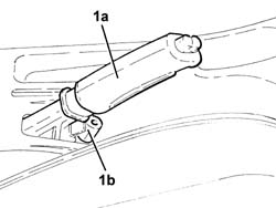
1. Lift up the handbrake lever (1a) and undo the handbrake cable tensioning nut (1b).
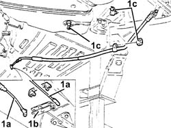
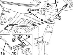
1. Disconnect the handbrake cables (1a) from the mounting bracket (1b) and from the fastenings on the fuel tank (1c).
Proceed with the removal
Op. 1076B20 REAR EXHAUST SILENCER - R + R.
Proceed with the removal
Op. 1076B24 INTERMEDIATE EXHAUST SILENCER - R + R.
Remove the heat shield for the exhaust pipe.
1. Position a hydraulic jack under the rear suspension crossmember.
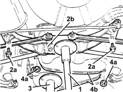
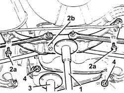
2. Undo the bolts (2a) and lower the rear suspension crossmember (2b) as far as necessary using the hydraulic jack.
3. Position a hydraulic jack with a suitable support under the fuel tank.
4. Undo the nuts (4a) fixing the fuel tank support belts (4b).
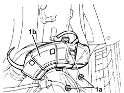
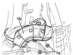
1. Undo the nuts (1a) and remove the protection (1b) for the fuel filler pipe after having released it from the bands.
1. Disconnect the rapid connectors for the fuel vapour supply pipes from the float valves to the fuel vapour separator.
2. Open the band and disconnect the fuel filler pipe from the tank.
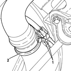
1. Disconnect the rapid connector for the fuel vapour supply pipe from the multifunction valve to the fuel vapour filter.
2. Disconnect the rapid connector for the rear fuel supply pipe, front fuel supply pipe side.
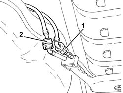
Lower the hydraulic jack and remove the fuel tank complete with rear fuel supply pipe and, if necessary, separate them at the bench.
Refitting
Place the fuel tank assembly back in its housing using the hydraulic jack.
Tighten the nuts fixing the fuel tank support belts.
Remove the hydraulic jack from beneath the fuel tank.
Connect the rapid connector for the rear fuel supply pipe, front fuel supply pipe side.
Connect the rapid connector for the fuel vapour supply pipe from the multifunction valve to the fuel vapour filter.
Connect the rapid connectors for the fuel vapour supply pipes from the float valves to the fuel vapour separator.
Connect the fuel filler pipe to the tank and secure it using the band.
Place the protection for the fuel filler pipe in position and secure it using the bands and the nuts.
Place the rear suspension crossmember in position using the hydraulic jack and secure it tightening the bolts to the recommended torque.
| Fastening | Component | Ø | Value (daNm) | |
|---|---|---|---|---|
| Bolt | REAR CROSS-BEAM | M10 | (Bodyshell side) 5.9 - 7.2 |
Remove the hydraulic jack from underneath the rear suspension crossmember.
Place the heat shield for the exhaust pipe in position.
Proceed with the refitting
Op. 1076B24 INTERMEDIATE EXHAUST SILENCER - R + R.
Proceed with the refitting
Op. 1076B20 REAR EXHAUST SILENCER - R + R.
Connect the handbrake cables to the mounting bracket and to the fastenings on the fuel tank.
Adjust handbrake lever travel
Op. 3380A04 HANDBRAKE - CHECK TRAVEL.
Place the handbrake lever boot in position.
Proceed with the refitting
Op. 1040A70 SUBMERGED PUMP ASSEMBLY COMPLETE WITH LEVEL GUAGE CONTROL - R + R.
Proceed with the refitting
Op. 7050A22 REAR SEAT CUSHION - R+R.
Proceed with the refitting
Op. 7050A15 SPLIT REAR SEAT RIGHT SQUAB R R.
Proceed with the refitting
Op. 7050A13 SPLIT REAR SEAT LEFT SQUAB R R.
Proceed with the refitting
Op. 7040B10 LOAD PLATFORM (LUGGAGE PLATFORM) TRIM - R+R.
Proceed with the refitting
Connect the negative battery terminal (-).
Remove the vehicle from the lift.
Removing
Position the vehicle on a lift.
Make sure that the ignition key is in the OFF position, then disconnect the negative battery terminal.
| Description | Connector | |
|---|---|---|
| Battery | See A1B BATTERY ( BATTERY NEGATIVE ) |
Proceed with the removal
Op. 1040A70 SUBMERGED PUMP ASSEMBLY COMPLETE WITH LEVEL GUAGE CONTROL - R + R.
Draw off the fuel from the tank using a special tool.
Release the handbrake boot and remove it.
1. Lift up the handbrake lever (1a) and undo the handbrake cable tensioning nut (1b).
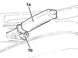
Proceed with the removal
Op. 1076B22 REAR EXHAUST SILENCER - R+R EMISSION CONTROL VERSIONS.
Proceed with the removal
Op. 1076B26 INTERMEDIATE EXHAUST SILENCER - R+R EMISSION CONTROL VERSIONS.
1. Undo the fastenings and remove the intermediate heat shield for the exhaust pipe.
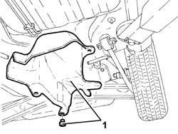
Proceed with the removal
Op. 4450B08 RIGHT REAR WHEEL R R.
1. Position a hydraulic jack under the rear suspension crossmember.
2. Undo the bolts (2a) and lower the rear suspension crossmember (2b) as far as necessary using the hydraulic jack.
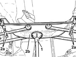
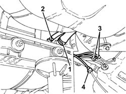
1. Open the band and disconnect the fuel filler pipe from the tank.
2. Loosen the band and disconnect the fuel reflux pipe from the tank.
3. Disconnect the rapid connectors for the fuel vapour supply pipes from the float valves to the fuel vapour separator.
4. Disconnect the rapid connector for the fuel vapour supply pipe from the multifunction valve to the fuel vapour filter.
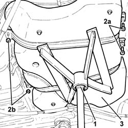
1. Position a hydraulic jack with a suitable support under the fuel tank.
2. Undo the bolts (2a) and the nuts (2b) fixing the fuel tank support belts.
3. Lower the hydraulic jack and remove the fuel tank.
Refitting
Place the fuel tank back in its housing using the hydraulic jack.
Tighten the bolts and the nuts fixing the fuel tank support belts.
Remove the hydraulic jack from beneath the fuel tank.
Connect the rapid connector for the fuel vapour supply pipe from the multifunction valve to the fuel vapour filter.
Connect the rapid connectors for the fuel vapour supply pipes from the float valves to the fuel vapour separator.
Connect the fuel reflux pipe to the tank and secure it using the band.
Connect the fuel filler pipe to the tank and secure it using the band.
Place the rear suspension crossmember in position using the hydraulic jack and secure it tightening the bolts to the recommended torque.
| Fastening | Component | Ø | Value (daNm) | |
|---|---|---|---|---|
| Bolt | REAR CROSS-BEAM | M10 | (Bodyshell side) 5.8 - 7.2 |
Remove the hydraulic jack from underneath the rear suspension crossmember.
Proceed with the refitting
Op. 4450B08 RIGHT REAR WHEEL R R.
Place the intermediate heat shield in position and secure it.
Proceed with the refitting
Op. 1076B26 INTERMEDIATE EXHAUST SILENCER - R+R EMISSION CONTROL VERSIONS.
Proceed with the refitting
Op. 1076B22 REAR EXHAUST SILENCER - R+R EMISSION CONTROL VERSIONS.
Adjust handbrake lever travel
Op. 3380A04 HANDBRAKE - CHECK TRAVEL.
Place the handbrake lever boot in position.
Proceed with the refitting
Op. 1040A70 SUBMERGED PUMP ASSEMBLY COMPLETE WITH LEVEL GUAGE CONTROL - R + R.
Connect the negative battery terminal (-).
Remove the vehicle from the lift.
Removing
Position the vehicle on a lift.
Make sure that the ignition key is in the OFF position, then disconnect the negative battery terminal.
| Description | Connector | |
|---|---|---|
| Battery | See A1B BATTERY ( BATTERY NEGATIVE ) |
Proceed with the removal
Proceed with the removal
Op. 7040B10 LOAD PLATFORM (LUGGAGE PLATFORM) TRIM - R+R.
Proceed with the removal
Op. 7050A13 SPLIT REAR SEAT LEFT SQUAB R R.
Proceed with the removal
Op. 7050A15 SPLIT REAR SEAT RIGHT SQUAB R R.
Proceed with the removal
Op. 7050A22 REAR SEAT CUSHION - R+R.
Proceed with the removal
Op. 1040A70 SUBMERGED PUMP ASSEMBLY COMPLETE WITH LEVEL GUAGE CONTROL - R + R.
Draw off the fuel from the tank using a special tool.
Release the handbrake boot and remove it.
1. Lift up the handbrake lever (1a) and undo the handbrake cable tensioning nut (1b).
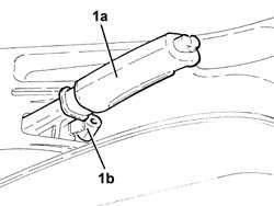
1. Disconnect the handbrake cables (1a) from the mounting bracket (1b) and from the fastenings on the fuel tank (1c).
Proceed with the removal
Op. 1076B20 REAR EXHAUST SILENCER - R + R.
Proceed with the removal
Op. 1076B18 RIGID SECTION OF EXHAUST PIPE BETWEEN CATALYTIC CONVERTER AND SILENCER - R + R.
Remove the heat shield for the exhaust pipe.
1. Position a hydraulic jack under the rear suspension crossmember.
2. Undo the bolts (2a) and lower the rear suspension crossmember (2b) as far as necessary using the hydraulic jack.
3. Position a hydraulic jack with a suitable support under the fuel tank.
4. Loosen the nuts fixing the fuel tank support belts.
1. Undo the nuts (1a) and remove the protection (1b) for the fuel filler pipe after having released it from the bands.
1. Open the band and disconnect the fuel filler pipe from the tank.
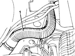
Lower the hydraulic jack and remove the fuel tank.
Refitting
Place the fuel tank back in its housing using the hydraulic jack.
Tighten the bolts and the nuts fixing the fuel tank support belts.
Remove the hydraulic jack from beneath the fuel tank.
Connect the fuel filler pipe to the tank and secure it using the band.
Place the rear suspension crossmember in position using the hydraulic jack and secure it tightening the bolts to the recommended torque.
| Fastening | Component | Ø | Value (daNm) | |
|---|---|---|---|---|
| Bolt | REAR CROSS-BEAM | M10 | (Bodyshell side) 5.9 - 7.2 |
Remove the hydraulic jack from underneath the rear suspension crossmember.
Place the heat shield in position and secure it.
Proceed with the refitting
Op. 1076B18 RIGID SECTION OF EXHAUST PIPE BETWEEN CATALYTIC CONVERTER AND SILENCER - R + R.
Proceed with the refitting
Op. 1076B20 REAR EXHAUST SILENCER - R + R.
Connect the handbrake cables to the mounting bracket and to the fastenings on the fuel tank.
Adjust handbrake lever travel
Op. 3380A04 HANDBRAKE - CHECK TRAVEL.
Place the handbrake lever boot in position.
Proceed with the refitting
Op. 1040A70 SUBMERGED PUMP ASSEMBLY COMPLETE WITH LEVEL GUAGE CONTROL - R + R.
Proceed with the refitting
Op. 7050A22 REAR SEAT CUSHION - R+R.
Proceed with the refitting
Op. 7050A15 SPLIT REAR SEAT RIGHT SQUAB R R.
Proceed with the refitting
Op. 7050A13 SPLIT REAR SEAT LEFT SQUAB R R.
Proceed with the refitting
Op. 7040B10 LOAD PLATFORM (LUGGAGE PLATFORM) TRIM - R+R.
Proceed with the refitting
Connect the negative battery terminal (-).
Remove the vehicle from the lift.
Removing
- Position the vehicle on a lift.
- Make sure that the ignition key is in the OFF position, then disconnect the battery terminal (-).
| Description | Connector | |
|---|---|---|
| Battery | See A001 Battery |
- Op. 7040H80 PARCEL RACK
- Op. 7040B10 LOAD PLATFORM (LUGGAGE PLATFORM) TRIM - R+R
- Op. 7050A13 SPLIT REAR SEAT LEFT SQUAB R R
- Op. 7050A15 SPLIT REAR SEAT RIGHT SQUAB R R
- Op. 7050A22 REAR SEAT CUSHION - R+R
- Op. 1040A70 SUBMERGED PUMP ASSEMBLY COMPLETE WITH LEVEL GUAGE CONTROL - R + R
- Draw off the fuel from the tank using a special tool.
- Release the handbrake boot and remove it.
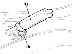
- Lift up the handbrake lever (1a) and undo the handbrake cable tensioning nut (1b).
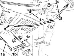
- Disconnect the handbrake cables (1a) from the mounting bracket (1b) and from the fastenings on the fuel tank (1c).
- Op. 1076B20 REAR EXHAUST SILENCER - R + R
- Op. 1076B24 INTERMEDIATE EXHAUST SILENCER - R + R
- Remove the heat shield for the exhaust pipe.
- Position a hydraulic jack under the rear suspension crossmember.
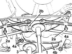
- Undo the bolts (2a) and lower the rear suspension crossmember (2b) as far as necessary using the hydraulic jack.
- Position a hydraulic jack with a suitable support under the fuel tank.
- Undo the nuts (4a) fixing the fuel tank support belts (4b).
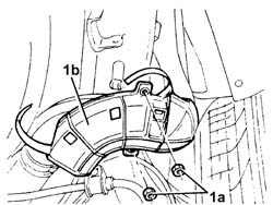
- Undo the nuts (1a) and remove the protection (1b) for the fuel filler pipe after having released it from the bands.
- Disconnect the rapid connectors for the fuel vapour supply pipes from the float valves to the fuel vapour separator.
- Open the band and disconnect the fuel filler pipe from the tank.
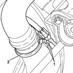
- Disconnect the rapid connector for the fuel vapour supply pipe from the multifunction valve to the fuel vapour filter.
- Disconnect the rapid connector for the rear fuel supply pipe, front fuel supply pipe side.
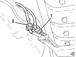
- Lower the hydraulic jack and remove the fuel tank complete with rear fuel supply pipe and, if necessary, separate them at the bench.
Refitting
- Place the fuel tank assembly back in its housing using the hydraulic jack.
- Tighten the nuts fixing the fuel tank support belts.
- Remove the hydraulic jack from beneath the fuel tank.
- Connect the rapid connector for the rear fuel supply pipe, front fuel supply pipe side.
- Connect the rapid connector for the fuel vapour supply pipe from the multifunction valve to the fuel vapour filter.
- Connect the rapid connectors for the fuel vapour supply pipes from the float valves to the fuel vapour separator.
- Connect the fuel filler pipe to the tank and secure it using the band.
- Place the protection for the fuel filler pipe in position and secure it using the bands and the nuts.
- Place the rear suspension crossmember in position using the hydraulic jack and secure it tightening the bolts to the recommended torque.
| Fastening | Component | Ø | Value (daNm) | |
|---|---|---|---|---|
| Bolt | REAR CROSS-BEAM | M10 | 5.9 - 7.2, daNm |
- Remove the hydraulic jack from underneath the rear suspension crossmember.
- Place the heat shield for the exhaust pipe in position.
- Op. 1076B24 INTERMEDIATE EXHAUST SILENCER - R + R
- Op. 1076B20 REAR EXHAUST SILENCER - R + R
- Connect the handbrake cables to the mounting bracket and to the fastenings on the fuel tank.
- Op. 3380A04 HANDBRAKE - CHECK TRAVEL
- Place the handbrake lever boot in position.
- Op. 1040A70 SUBMERGED PUMP ASSEMBLY COMPLETE WITH LEVEL GUAGE CONTROL - R + R
- Op. 7050A22 REAR SEAT CUSHION - R+R
- Op. 7050A15 SPLIT REAR SEAT RIGHT SQUAB R R
- Op. 7050A13 SPLIT REAR SEAT LEFT SQUAB R R
- Op. 7040B10 LOAD PLATFORM (LUGGAGE PLATFORM) TRIM - R+R
- Op. 7040H80 PARCEL RACK
- Connect the negative battery terminal (-).
- Remove the vehicle from the lift.
Parts & tools for this job Staging For 2003 Alfa Romeo GT
- PARTEngine gasket setSearch: Alfa Romeo GT 2003 engine gasket set
- TOOLTorque wrenchSearch: 3/8 inch torque wrench
- TOOLFeeler gauge setSearch: feeler gauge set
Links open Amazon search results in a new tab. As an Amazon Associate I earn from qualifying purchases.