
Transmission with joints included - r.r.
- Make
- Alfa Romeo
- Model
- Brera and Spider Factory Service Manual
- Year
- 2005–2010
- Section
- Transmission shaft › Transmission with joints included - r.r.
TRANSMISSION WITH JOINTS INCLUDED - R.R.
Removing
- Position the vehicle on a lift.
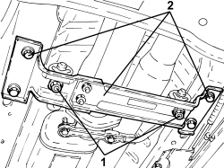
1. Undo the fastenings securing the catalyzer assembly to the mounting bracket.
2. Undo the bolts securing the catalyzer assembly mounting bracket to the bodyshell and remove it.
- Remove the gaskets.
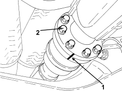
1. Mark the position of the two flanges connecting the rear drive idler casing (PTU) to the propeller shaft.
2. Undo the bolts fixing the two flanges connecting the PTU to the propeller shaft.
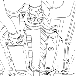
1. Unscrew the bolts securing the intermediate supports to the propeller shaft.
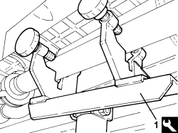
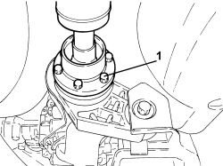
1. Position a hydraulic jack complete with support tool in the centre area of the propeller shaft.
| Tool | Description | Function | Validity |
|---|---|---|---|
| 1870602000 | Support | Propeller shaft mounting | 3.2 JTS |
- Mark the position of the two flanges connecting the rear differential (RDA) to the propeller shaft.
1. Undo the bolts fixing the propeller shaft to the RDA.
- Lower the hydraulic jack and remove the propeller shaft complete with joints.
- Keep any alignment spacers that may have been used for the propeller shaft intermediate supports.
It is advisable to use the same spacers during the refitting and procedure 2410D31 for checking the propeller shaft alignment.
Refitting
- Place the propeller shaft in its housing using the hydraulic jack fitted with the support tool as described below.
- Firstly insert the front section of the shaft passing over the suspension crossmember and fitting into the PTU front constant velocity joint flange.
- Straighten the shaft and feed the rear constant velocity joint flange into the RDA one.
- Continue lifting until the shaft is straightened placing the brackets in contact with the bodyshell.
The propeller shaft support tool should remain in position until the refitting is completed.
1. Fit the shaft alignment kit "spacer" by the rear joint.
| Tool | Description | Function | Validity |
|---|---|---|---|
| 2000011700 | Propeller shaft alignment kit | Propeller shaft alignment angles check | 3.2 JTS |
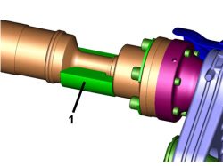
Only remove the spacer at the end of the refitting and procedure 2410D31 for checking the alignment of the propeller shaft.
- Align the reference marks, made during the removal, for the propeller shaft front constant velocity joint and the PTU flange.
- Align the reference marks, made during the removal, for the propeller shaft rear constant velocity joint and the RDA flange.
- Tighten the bolts fixing the front constant velocity joint to the PTU to a torque of 10% of the final value given below.
| Component | Fastening | dia | Value (daNm) | Validity |
|---|---|---|---|---|
| Propeller shaft - rear drive idler casing side | Bolt | M8 | 3.1 ÷ 3.7 | 3.2 JTS |
- The bolts should be tightened in a crossover sequence as illustrated.
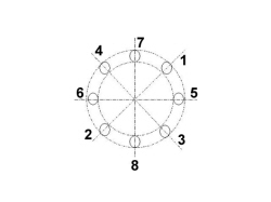
- Tighten the bolts fixing the rear constant velocity joint to the RDA with half-moon washers in between to a torque of 10% of the final value given below.
| Component | Fastening | dia | Value (daNm) | Validity |
|---|---|---|---|---|
| Propeller shaft - rear differential side | Bolt | M10 | 5.6 ÷ 6.8 | 3.2 JTS |
- The bolts should be tightened in a crossover sequence as illustrated.
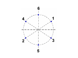
- Tighten the bolts fixing the propeller shaft intermediate supports to the bodyshell to a torque figure of 10% of the final value given below refitting any alignment spacers removed during the removal.
| Component | Fastening | dia | Value (daNm) | Validity |
|---|---|---|---|---|
| Bodyshell side propeller shaft intermediate support | Bolt | M8 | 2.2 ÷ 2.6 | 3.2 JTS |
- Tighten the bolts tightened previously securing the constant velocity joints and the propeller shaft intermediate supports to the final torque given below.
The final tightening of the constant velocity joint fixing bolts should be carried out in a crossover sequence as illustrated in the previous diagrams.
- Remove the hydraulic jack and support tool.
- Place the catalyzer assembly mounting bracket in position and secure it to the bodyshell by tightening the bolts to the recommended torque.
| Component | Fastening | dia | Value (daNm) | Validity |
|---|---|---|---|---|
| Catalyzer assembly to bodyshell mounting bracket | Bolt | M8 | 2.2 ÷ 2.7 | 3.2 JTS |
- Position the catalyzer assembly and secure it to the mounting bracket.
- Remove the vehicle from the lift.
Parts & tools for this job Staging For 2005 Alfa Romeo Brera
- TOOLTorque wrenchSearch: 3/8 inch torque wrench
- TOOLSocket setSearch: socket set metric
- BOOKHaynes manualSearch: Haynes manual Alfa Romeo Brera
Links open Amazon search results in a new tab. As an Amazon Associate I earn from qualifying purchases.