
Introduction - petrol direct fuel injection system
- Make
- Alfa Romeo
- Model
- Brera and Spider Factory Service Manual
- Year
- 2005–2010
- Section
- Petrol injection system › Introduction - petrol direct fuel injection system
INTRODUCTION - PETROL DIRECT FUEL INJECTION SYSTEM
Bosch MED 7.6.2 engine management control unit
It allows the integrated management of the engine injection and ignition; there are two connectors, one for the engine side wiring (connector A) and one for the vehicle side wiring (connector B).
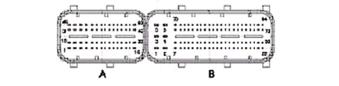
ENGINE SIDE 60 PIN CONNECTOR (A)
| PIN | FUNCTION |
|---|---|
| 1 | Ignition control earth |
| 2 | Right exhaust phase transformer solenoid |
| 3 | Right inlet phase transformer solenoid |
| 4 | Left exhaust phase transformer solenoid |
| 5 | Left inlet phase transformer solenoid |
| 6 | n.c. |
| 7 | Reference earth |
| 8 | Fuel pressure sensor signal |
| 9 | Flow meter reference earth |
| 10 | Motorized throttle position potentiometer signal (track 1) |
| 11 | Flow meter reference earth |
| 12 | Flow meter |
| 13 | Flow meter power supply |
| 14 | n.c. |
| 15 | Throttle actuator power supply |
| 16 | Earth for ignition coil modules 2-4-6 |
| 17 | Injector 3 earth |
| 18 | Injector 3 power supply |
| 19 | Injector 6 power supply |
| 20 | Injector 6 earth |
| 21 | Screening earth |
| 22 | Engine coolant temperature sensor signal |
| 23 | Absolute pressure sensor signal |
| 24 | Throttle position potentiometer power supply |
| 25 | Motorized throttle position potentiometer signal (track 2) |
| 26 | Power supply for: timing sensors, fuel pressure sensor, absolute pressure sensor, oil pressure sensor |
| 27 | Intake air temperature signal (in flow meter) |
| 28 | Engine oil pressure sensor signal |
| 29 | n.c. |
| 30 | Throttle actuator earth |
| 31 | Flow rate regulator |
| 32 | Injector 2 earth |
| 33 | Injector 2 power supply |
| 34 | Injector 5 power supply |
| 35 | Injector 5 earth |
| 36 | Engine rpm and TDC sensor |
| 37 | Exhaust camshaft cylinders 1-3-5 timing sensor signal |
| 38 | Exhaust camshaft cylinders 2-4-6 timing sensor signal |
| 39 | Ignition coil 4 module control |
| 40 | Ignition coil 5 module control |
| 41 | Ignition coil 6 module control |
| 42 | n.c. |
| 43 | Detonation sensor cylinders 2-4-6 |
| 44 | Detonation sensor cylinders 1-3-5 |
| 45 | n.c. |
| 46 | Canister solenoid valve |
| 47 | Injector 1 earth |
| 48 | Injector 1 power supply |
| 49 | Injector 4 power supply |
| 50 | Injector 4 earth |
| 51 | Engine rpm and TDC sensor |
| 52 | Inlet camshaft cylinders 1-3-5 timing sensor signal |
| 53 | Inlet camshaft cylinders 2-4-6 timing sensor signal |
| 54 | Ignition coil 1 module control |
| 55 | Ignition coil 2 module control |
| 56 | Ignition coil 3 module control |
| 57 | n.c. |
| 58 | Detonation sensor cylinders 2-4-6 |
| 59 | Detonation sensor cylinders 1-3-5 |
| 60 | Shut-off solenoid valve |
VEHICLE 94 PIN CONNECTOR (B)
| PIN | FUNCTION |
|---|---|
| 1 | Earth on bodyshell |
| 2 | Earth on bodyshell |
| 3 | Power supply |
| 4 | Earth on bodyshell |
| 5 | Power supply |
| 6 | Power supply |
| 7 | n.c. |
| 8 | Petrol pump relay positive control |
| 9 | n.c. |
| 10 | n.c. |
| 11 | A/C compressor engagement request |
| 12 | Compressor engagement relay |
| 13 | n.c. |
| 14 | Brake lights control signal |
| 15 | n.c. |
| 16 | Air conditioning linear pressure sensor negative |
| 17 | n.c. |
| 18 | n.c. |
| 19 | n.c. |
| 20 | Brake lights control |
| 21 | n.c. |
| 22 | n.c. |
| 23 | n.c. |
| 24 | n.c. |
| 25 | Main relay |
| 26 | n.c. |
| 27 | n.c. |
| 28 | n.c. |
| 29 | n.c. |
| 30 | n.c. |
| 31 | Screening earth |
| 32 | Clutch pedal switch |
| 33 | Cruise control resume signal from steering column switch unit |
| 34 | Cruise control +/set signal from steering column switch unit |
| 35 | Cruise control ON activation signal from steering column switch unit |
| 36 | n.c. |
| 37 | n.c. |
| 38 | Air conditioning linear pressure sensor signal |
| 39 | n.c. |
| 40 | n.c. |
| 41 | n.c. |
| 42 | n.c. |
| 43 | Cruise control signal from steering column switch unit |
| 44 | n.c. |
| 45 | n.c. |
| 46 | n.c. |
| 47 | n.c. |
| 48 | n.c. |
| 49 | n.c. |
| 50 | Sensor downstream of catalyzer cylinders 1-3-5 |
| 51 | Sensor upstream of pre-catalyzer cylinders 2-4-6 |
| 52 | Sensor downstream of catalyzer cylinders 2-4-6 |
| 53 | Sensor downstream of catalyzer cylinders 2-4-6 |
| 54 | |
| 55 | Sensor upstream of pre-catalyzer cylinders 1-3-5 |
| 56 | Sensor upstream of pre-catalyzer cylinders 1-3-5 |
| 57 | Sensor upstream of pre-catalyzer cylinders 2-4-6 |
| 58 | Sensor upstream of pre-catalyzer cylinders 2-4-6 |
| 59 | Accelerator pedal potentiometer negative (track 1) |
| 60 | Accelerator pedal potentiometer signal (track 1) |
| 61 | Power supply for: accelerator pedal potentiomter (track 1) and air conditioning linear pressure sensor |
| 62 | n. c. |
| 63 | C-CAN H (at NFR) |
| 64 | C-CAN H (at NBC) |
| 65 | n. c. |
| 66 | n. c. |
| 67 | NT/1 from CVM |
| 68 | M.I.L. warning light at NQS |
| 69 | n. c. |
| 70 | Relay feed for engine cooling fan high speed |
| 71 | n. c. |
| 72 | n. c. |
| 73 | Sensor upstream of pre-catalyzer cylinders 1-3-5 |
| 74 | Sensor downstream of catalyzer cylinders 1-3-5 |
| 75 | Sensor downstream of catalyzer cylinders 1-3-5 |
| 76 | n. c. |
| 77 | Sensor upstream of pre-catalyzer cylinders 1-3-5 |
| 78 | Sensor upstream of pre-catalyzer cylinders 1-3-5 |
| 79 | Sensor upstream of pre-catalyzer cylinders 2-4-6 |
| 80 | Sensor upstream of pre-catalyzer cylinders 2-4-6 |
| 81 | Accelerator pedal potentiometer negative (track 2) |
| 82 | Accelerator pedal potentiometer signal (track 2) |
| 83 | Accelerator pedal potentiometer power supply (track 2) |
| 84 | n. c. |
| 85 | C-CAN L (at NFR) |
| 86 | C-CAN L (at NBC) |
| 87 | K line |
| 88 | n. c. |
| 89 | Relay feed for engine cooling fan low speed |
| 90 | n. c. |
| 91 | n. c. |
| 92 | Power supply from battery (+30) |
| 93 | W Line |
| 94 | Sensor downstream of catalyzer cylinders 2-4-6 |
HDP 2.5 high pressure pump
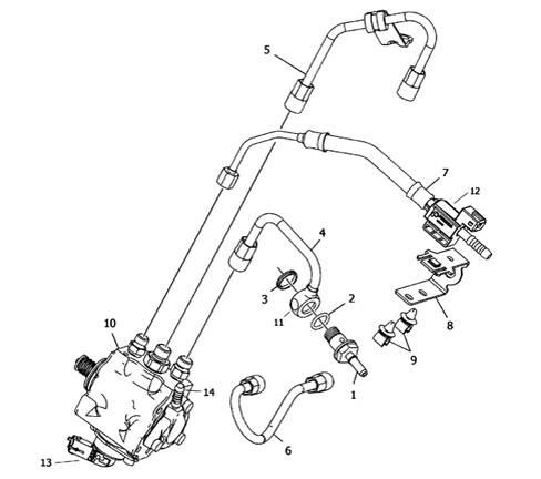
1. Low pressure fuel supply pipe connector.
2. Sealing ring.
3. Sealing ring, rail side.
4. Pressure pump supply pipe.
5. High pressure supply pipe to left rail
6. High pressure connecting pipe between left and right rails
7. Fuel return pipe to tank
8. Fuel pipe bracket
9. Fuel pipe bracket clip
10. High pressure pump
11. Eyelet connecting low pressure supply pipe to rail
12. Shut-off solenoid valve
13. High pressure pump outlet flow rate regulator
14. Petrol vapour recovery from damper
The high pressure pump is fitted on the left head and is controlled by the exhaust side camshaft by means of a three lobe cam which activates a pumping element inside the pump; the pumping element is activated three times for each revolution of the camshaft.
The high pressure pump has a diaphragm damper connected with the low pressure supply chamber to limit the supply duct impulses. The petrol vapours that are produced at this damper are collected in a special pipe which is later connected to the fuel return pipe to the tank.
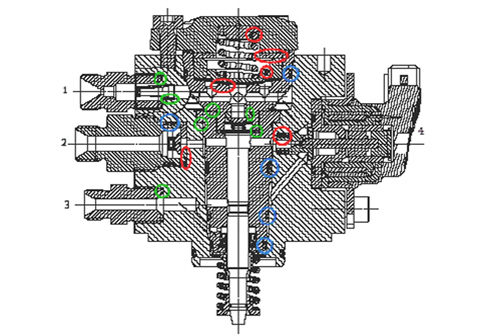
1. Low pressure supply (6 bar)
2. High pressure supply
3. Fuel return to the tank
4. Flow rate regulator
The diagram of the pump above highlights the contact points between the removable parts in red, the connection points with the metal seals or plastic deflectors in green and the location of the internal o-rings in blue.
The flow rate regulator, controlled by the control unit, which has the task of regulating the fuel high pressure, is located on the pressure pump. In particular, the needle for this regulator controls the closing of the (exhaust) port for the fuel from the high pressure chamber to the low pressure chamber for returning to the tank. To control the high pressure, the control unit closes the above mentioned port starting from a given distance of the pumping element stroke. In practice, if the port is left open for the entire duration of the pumping element stroke, the fuel is all sent to the supply circuit without an increase in the pressure in relation to the intake connected to the tank. If, on the other hand, the port is kept closed for the entire duration of the stroke, the pump is then working at maximum efficiency. For example, if the control unit decides to implement a 50% efficiency, it will control the closing of the exhaust port starting halfway along the pumping element stroke. If the regulator cannot be controlled by the control unit, the pump remains in the minimum efficiency position without producing a rise in pressure.
It can be deduced that in order to manage the fuel pressure, the engine management control unit needs to know the distance of the piston stroke in order to decide when to control the closing of the exhaust port. This information is obtained by the engine management control unit on the basis of the analysis of the top dead centre (rpm) signal for the crankshaft and the signal for the camshaft operating the pump.
The shut-off valve which intercepts the return flow of fuel to the tank is located on the fuel return pipe to the tank; this solenoid valve is only "open" with the engine started, whilst it is "closed" with the engine off or the ignition on. Its function is to prevent the draining of the high pressure pump to facilitate engine starting.
Diagram showing pump internal connections
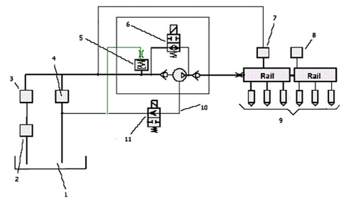
1. Tank
2. Low pressure pump
3. Filter
4. Low pressure regulation valve (6 bar)
5. Damper
6. Flow rate regulator
7. Maximum pressure valve (120 bar)
8. Fuel high pressure sensor
9. Injectors
10. Fuel return pipe
11. Shut-off valve
Fuel manifold (rail) for left cylinder head
It is connected to the pressure pump supply pipe and has a connector for connecting the rigid supply pipe to the right head rail. The maximum fuel pressure valve calibrated at 120 bar is also located on the rail.
The pressure pump supply pipe is connected, before reaching the pump, to the left rail by means of a spherical connector. In this way the pressure pump intake is in contact with a duct inside the rail, in turn connected to a chamber normally closed by the maximum pressure valve. When, for any reason, the maximum pressure valve intervenes (opens), the high pressure in the rail is discharged directly into the low pressure supply pipe for the pump by means of the connection mentioned above.
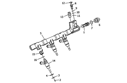
1. Fuel rail opening
2. Injector sealing ring
3. Injector seat alignment ring
4. Injector alignment ring
5. Left rail
6. Connector for high pressure connecting pipe between left and right rails
7. Sealing ring
8. Maximum pressure valve
9. Maximum pressure valve upper o-ring
10. Maximum pressure valve seal
11. Maximum pressure valve lower o-ring
12. Maximum pressure valve circlip
13. High pressure pipe connector (from high pressure pump)
14. Injector
15. Injector retaining clip
16. Injector upper o-ring
Fuel manifold (rail) for right cylinder head
The right rail receives the high pressure fuel by means of a rigid pipe that connects it to the other rail. The fuel pressure sensor is located on it.
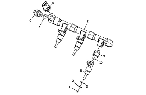
1. Sealing ring
2. Injector seat alignment ring
3. Injector alignment ring
4. Fuel pressure sensor
5. Right rail
6. Connector for high pressure connecting pipe between left and right rails
7. Sealing ring
8. Injector
9. Injector retaining clip
10. Injector upper o-ring
Throttle body for electronic accelerator system
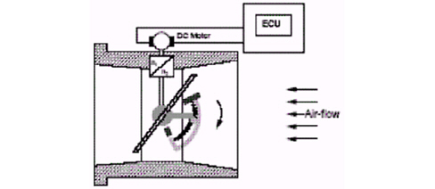
Specifications
The throttle body includes the actuator, the throttle valve and the throttle position potentiometers (pontentiometers 1 and 2) incorporated in a single casing.
The actuator consists of a direct current motor with a dual stage gear that controls the position of the throttle valve thereby controlling the flow of engine intake air; the actuator works within a current range that determines the movement of the throttle from the minimum closing position to the maximum opening position; if there is a fault, the throttle valve returns to its lower mechanical stop position.
PIN OUT
| DESCRIPTION | Pin Connector Component | Pin Connector Control unit (Engine side connector) |
|---|---|---|
| Actuator | 1 | 15 |
| Actuator | 4 | 30 |
| Power supply for potentiometers 1 and 2 | 3 | 3 |
| Potentiometer 1 signal | 6 | 6 |
| Potentiometers 1 and 2 earth | 2 | 9 |
| Potentiometer 2 signal | 5 | 5 |
Accelerator pedal potentiometer
Specifications
The sensor consists of a casing secured to the accelerator pedal; the case contains an axially-located shaft connected to two potetiometers: a main one and one safety one.
A coil spring on the shaft ensures the correct amount of resistance to pressure while a second spring ensures return following release.
Operation
The accelerator pedal position is converted into an electrical voltage signal and sent to the control unit by the potentiometer connected to the pedal.
Fuel pump in the tank
There is a low pressure pump inside the fuel tank with a mechanical pressure regulator in parallel that allows the supply of the high pressure pump by means of a pipe. The supply pressure for the low pressure pump is 6 bar; the fuel return pipe from the high pressure pump recovery chamber also reaches the tank.
Specifications
The fuel pump is equipped with a permanent magnet electric motor that controls the pump and a terminal mount cover that contains the electrical and hydraulic connections.
The pump stage is single, peripheral flow type with high performance under low voltage and temperature conditions.
The advantages compared to pumps that operate on volumetric princples are that they are lighter and smaller.
Canister solenoid valve (petrol vapour flow)

The valve is used to regulate the flow of fuel vapours coming from the active charcoal filter by means of a signal received by the injection control unit.
Flow rate regulator
The flow rate regulator, fitted on the high pressure fuel pump, has the task of regulating the pump outlet flow rate on the basis of maps stored inthe control unit memory and the engine operating conditions; the wiring diagram showing the connection with the engine management control unit is illustrated below.
Specifications
Output voltage: 2V
Rest position: normally open (not controlled)
Operating pressure range: 6 – 120 bar
During the normal working cycle the closing of the regulator is operated by the control unit three times for every camshaft revolution.
Shut-off solenoid valve
Specifications
The solenoid valve is located on the fuel return pipe to the tank from the high pressure pump, in this way intercepting the return fuel flow to the tank; this solenoid valve is only "open" with the engine started, whilst it is "closed" with the engine off or the ignition on. Its function is to prevent the draining of the high pressure pump to facilitate engine starting.
High pressure injectors

Function
To ensure the injection of fuel into the cylinder in direct petrol injection systems.
Specifications
The injectors are the high pressure electromagetic type with a compact 2 pin connector and are connected directly to the injection manifold and spray directly into the combustion chamber. The opening time for the injectors and the quantity of fuel injected are managed by the electric control signal for the actual injectors; there is a wiring diagram below showing the connection with the engine management control unit; the injectors have the number of the cylinder to which they belong.
Mechanical properties:
Operating (maximum) pressure: 120 bar
Flow rate: 20 cc / minute
Maximum temperature at injector nozzle: <170°C
Electrical properties:
Start of opening voltage: 72V
Start of opening current: 8,2 – 10,5
Peak current: 5,4 – 7,9
Peak time: 490 – 510 microseconds
Maintenance current: 2,6 – 4,4
Internal resistance: 0.8 Ohm
High pressure fuel sensor

Function
To measure the pressure of the fuel in the rail, supplying the injection control unit with a feedback signal for regulating the pressure and the duration of the injection.
Specifications:
it is a piezoelectric pressure sensor, located on the right fuel rail, comprising a mixed metal and plastic casing. The metal part includes a diaphgram pressure meter; the plastic part contains the 3 pin connector; the wiring digram illustrating the connection with the engine management control unit is below.
Specifications:
Pressure range: 0 -140 bar
Response time: 2 ms.
Supply voltage: 5 V
Supply current: 12 mA.
Signal:
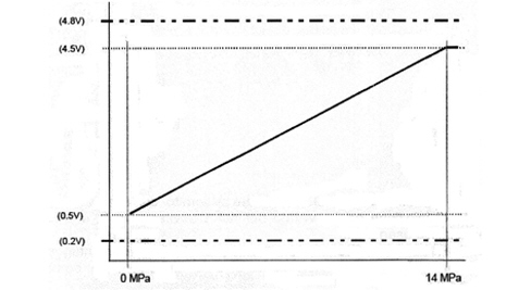
Voltage varies according to pressure value measured; the typical response is the linear type from 0.5 V (0 bar) to 4.5 V (140 bar).
The typical output signal response is given below:
Ignition coils
Specifications
the ignition system has one coil for each cylinder; the power module is built-into the coil; the wiring diagram showing the connection with the engine management control unit is illustrated below; the coils have a number that identifies the cylinder to which they belong.
Engine rpm sensor

Function:
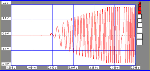
to provide the engine managment control unit with the rotation speed and angular position signal for the crankshaft.
Specifications:
the sensor is the inductive type and comprises a casing with a metal coil and a 2 pin connector.
Operation
the changeover from full to empty determined by the presence or absence of a tooth for the flywheel fitted on the crankshaft brings about a magnetic flux change sufficient to generate an induced alternating voltage proportional to the number of teeth on the phonic wheel.
The frequency of the voltage sent to the electronic control unit provides it with the measurement of the crankshaft angular speed; the wiring diagram for the connection with the engine management control unit is illustrated below.
Positioning
the sensor is located on the right side of the crankcase, towards the flywheel: it is facing the flywheel on the crankshaft.
The specifications of the signal are described below:
Camshaft timing sensors
Function:
To allow the engine management control unit to recognize which cylinder is at the end of the compression stroke.
Specifications:
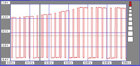
The timing sensors are the Hall effect type, made up of a casign that contains a matching element and a 3 pin connector, a magnet and a signal acquisition circuit.
There are four sensors, one for each camshaft.
Positioning:
The timing sensors are located opposite the camshafts.
The wiring diagram showing the connection with the engine management control unit is illustrated below.
Supply: 5V
Signal type: Variable voltage signal in time, maximum value and frequency depending on a square wave;
The specifications of the signal are described below
Detonation sensors

Specifications:
these are piezoelectrical type sensors fitted directly with a compact connector. There are two sensors, one on the right bank and one on the left bank. They measure the intensity of the vibrations produced by the mechanical pressure in the cylinders.
Engine coolant temperature sensor
Specifications:
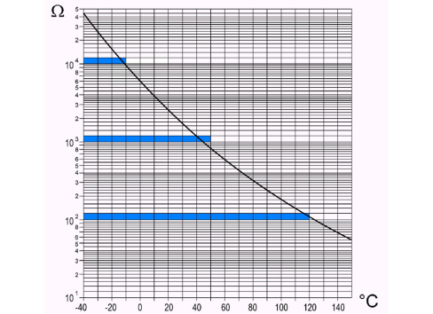
Sensor measuring the temperature of the engine coolant, with 2 pins, with an operating range of –40°C to 130°C.
Positioning:
The sensor is located on the outer part of the left cylinder headl;
Electrical properties:
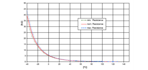
Sensor type: the sensor consists of an NTC thermistor
Resistance: variable from a maximum of 45 kOhm at -40°C to 60 Ohm at 150°C.
The variation in the resistance depending on the temperature is described below.
Oil pressure sensor
Specifications:
the oil pressure sensor is the linear type and is fitted on the oil filter mounting assembly.
Oil level and temperature sensor
Specifications:
The sensor controls the level and the temperature of the lubricant oil inside the oil sump fitted under the mono bloc.
This sensor is not connected to the engine management control unit but to a coupling which interfaces with the Instrument Panel Node (NQS).
Intake air temperature and flow rate meter
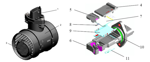
1. Connector
2. Cylindrical casing
3. Protective grille
4. Circuit cover
5. Air flow measuring duct cover
6. Measuring flow duct
7. Circuit
8. Sensitive element
9. Circuit fitting base
10. O-ring
11. Temperature sensor
Specifications:
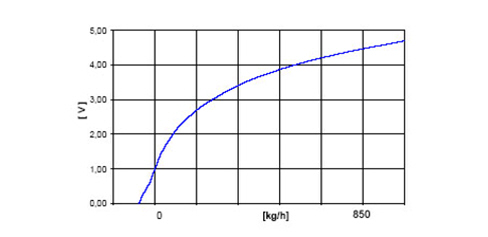
the HFM5 intake air flow meter is the analogue type and is fitted on the engine air intake pipe, upstream of the throttle body and the intake chamber; the connector connected to the engine wiring has five pins; the additional protective grille (3) ensures maximum protection against the impurities in the intake air flow;
Typical intake air flow rate curve
Typical intake air temperature curve
Absolute pressure sensor
Specifications:
The sensor is located on the intake chamber and measures the pressure in the intake manifold; its function is to improve the engine carburation carried out by the control unit in fast shifts (sudden changes in engine speed and load conditions); it is basically considered, however, as a small refining implemented by the control unit in the above conditions calculated on the basis of the intake flow rate signal coming from the flow meter.
Parts & tools for this job Staging For 2005 Alfa Romeo Brera
- PARTFuel filterSearch: Alfa Romeo Brera 2005 fuel filter
- TOOLFuel pressure test kitSearch: fuel pressure test kit
- TOOLFuel line disconnect toolSearch: fuel line disconnect tool
Links open Amazon search results in a new tab. As an Amazon Associate I earn from qualifying purchases.