
Introduction - exhaust emission control system
- Make
- Alfa Romeo
- Model
- Brera and Spider Factory Service Manual
- Year
- 2005–2010
- Section
- Emission control system › Introduction - exhaust emission control system
INTRODUCTION - EXHAUST EMISSION CONTROL SYSTEM
Exhaust gas oxygen sensor upstream of the pre-catalyzer
Specifications:
the sensor is the LSU 4.2 broad band linear type with a built-in heater and can operate in a range that goes from 0.7 Lambda to the air. Two of this type of sensor are used, one located upstream of the right bank pre-catalyzer and one upstream of the left bank pre-catalyzer; the two sensors detect the residual oxygen in the exhaust gases after combustion. A module integrated in the control unit, shown in the diagram below, is required for the operation of the sensor.
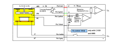
On the left of the diagram it is possible to see the actual part of the oxygen sensor proper, whilst on the right the control module in the control unit can be seen with the two elements connected by means of wiring which is also visible in the diagram.
The information concerning the quality of the exhaust gas is made up of the value of the pumping current lp which passes through the cable connected to pin 6 shown in the diagram in red; inside the module the voltage signal coming from pin 1 is sent to an amplifier where it is compared with a reference voltage of 450 mV, suitably produced at pin 5, by two generators in the module; in stoichiometric mixture conditions, the voltage signal at pin 1 proportional to the quantity of oxygen present in the exhaust gases in the sensor is equal to around 450 mV, therefore the algebraic total coming out of the amplifier connected to pins 5 and 1 is nil (450 mV - 450 mV), therefore the output does not have a pumping current "lp" capable of flowing through the branch circuit connected to pin 6 and arriving at the sensor.
If the mixture strength is not stoichiometric, the voltage coming from pin 1 is not 450 mV, therefore in this case the pumping current "lp" leaving the amplifier is not zero and it flows into the branch connected to pin 6 and on arriving at the sensor pumping cell produces a migration of oxygen ions which re-establishes the balance that existed in stoichiometric conditions; clearly, depending on whether the mixture is weak or rich, the direction of the pumping current changes, in any case the value of the pumping current lp is proportional to how weak or righ the mixture in the cylinder is (was), because it constitutes the current that was necessary to re-establish the actual balance in stoichiometric conditions.
This type of sensor is therefore particularly useful in giving the control unit very precise information on the quality of the combustion and, especially, its outcome, allowing the control unit to make very accurate corrections to the carburation. There is an internal electrical heater, for optimum operation of the sensor, connected to pins 3 and 4 which is designed to keep the internal operating temperature optimum. There is a sensor calibration resistance inside the connector, connected to pin 2, designed to calibrate the sensor during production in a controlled atmosphere; a feature of the connector is the small Gore-Tex area through which reference air required by the sensor for correct operation can flow via the wiring.
The wiring diagram below illustrates the connection with the engine management control unit.
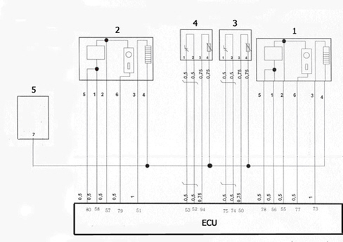
1. Lambda sensor upstream of pre-catalyzer cylinders 1, 3, 5 (right bank)
2. Lambda sensor upstream of pre-catalyzer cylinders 2, 4, 6 (left bank)
3. Lambda sensor downstream of pre-catalyzer cylinders 1, 3, 5 (right bank)
4. Lambda sensor downstream of pre-catalyzer cylinders 2, 4, 6 (left bank)
5. Engine compartment junction unit
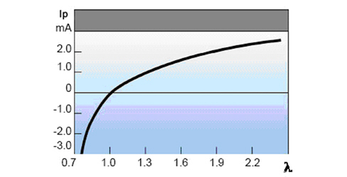
Typical curve for sensor pumping current
The graph below shows the variation in the pumping current depending on the Lambda value which notifies the control unit whether the mixture is rich or lean.
Exhaust gas oxygen sensor downstream of the catalyzer
Specifications:
The exhaust gas oxygen sensors downstream of the catalyzer have the task of diagnosing the efficiency of the cztalyzers on the exhaust pipes. Two sensors are used, one downstream of the catalyzer for the exhaust pipe for the right bank cylinders and one downstream of the catalyzer for the exhaust pipe for the left bank cylinders. The connector has four pins; the wiring diagram showing the connection with the engine management control unit is illustrated below.
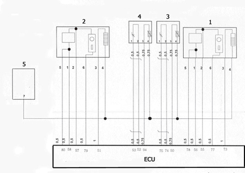
1. Lambda sensor upstream of pre-catalyzer cylinders 1, 3, 5 (right bank)
2. Lambda sensor upstream of pre-catalyzer cylinders 2, 4, 6 (left bank)
3. Lambda sensor downstream of pre-catalyzer cylinders 1, 3, 5 (right bank)
4. Lambda sensor downstream of pre-catalyzer cylinders 2, 4, 6 (left bank)
5. Engine compartment junction unit
DESCRIPTION OF COMPONENTS
CATALYTIC CONVERTER
Specifications
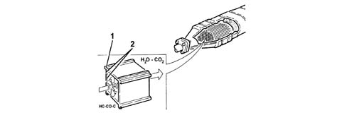
The catalytic converter is a post-treatment device for oxidizing the CO, HC and particles transforming them into carbon dioxide (CO2) and water vapour (H20).
The catalytic converter consists of a ceramic, honeycomb structure (1) with cells impregnated with platinum (2) which catalyzes the oxidation reactions.
Operation
The exhaust gases passing through the cells heat the catalyzer triggering off the conversion of the pollutants into inert compounds.
The oxidizing chemical reaction of the CO, HC and particles is effective at temperatures of between 200 and 350°C.
In effect, above 350°C the sulphur contained in the diesel fuel starts to oxidize producing sulphur dioxide and sulphur trioxide.
DPF SYSTEM (Diesel Particulate Filter)
This is a mechanical filter that "traps" the carbon particles (particulate) and the engine oil ashes in diesel engine exhaust gases.
The action of the DPF makes it possible to keep the level of carbon particles down by around 90% in line with Euro 4 and 5 regulations.
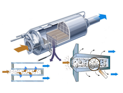
The operation of the DPF system is managed by the injection control unit by means of special strategies. In addition to the filter the DPF system comprises an exhaust gas temperature sensor and a differential pressure sensor.
The differential pressure sensor measures the pressure of the exhaust gases upstream and downstream of the filter, by means of special pipes, signalling the gradual accumulation of particulate to the control unit. The particulate accumulation process and increase in the pressure of the exhaust gases inside the filter depends on the engine load, the weight of the vehicle, the engine capacity and power. Therefore the occasional removal of the particulate is necessary, regenerating the filter by means of a procedure that makes use of multiple injections to increase the temperature of the exhaust gases (about 600°C) and consequently burn the particulate. The regeneration procedure is controlled by the injection control unit which acts: on the metering of the fuel (up to five injections in the same engine cycle per cylinder) and on the control of the air (E.G.R. and supercharging pressure).
The regeneration phase takes place in a few minutes and does not affect the continuity of the torque supplied by the engine compared with normal operation.
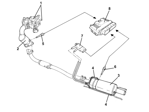
1. Turbocharger-exhaust manifold assembly
2. Catalytic converter
3. Filter
4. Exhaust gas pressure intake
5. Exhaust gas temperature sensor downstream of the catalyzer
6. Exhaust gas temperature sensor downstream of the filter
7. Differential pressure sensor
8. Injection control unit
Parts & tools for this job Staging For 2005 Alfa Romeo Brera
- PARTExhaust gasketSearch: Alfa Romeo Brera 2005 exhaust gasket
- TOOLPenetrating oilSearch: penetrating oil
- TOOLOBD2 scannerSearch: OBD2 scanner
Links open Amazon search results in a new tab. As an Amazon Associate I earn from qualifying purchases.