
Ultrasound/anti-lift module check
- Make
- Alfa Romeo
- Model
- Brera and Spider Factory Service Manual
- Year
- 2005–2010
- Section
- Special accessories › Ultrasound/anti-lift module check
ULTRASOUND/ANTI-LIFT MODULE CHECK
The ultrasound and antilift modules are located in the front courtesy light
| CHECK TO BE PERFORMED | RESOLUTION IF THE CHECK IS NOT OK | |
|---|---|---|
| 1 | Connect the diagnostic instrument in Voltmeter mode with the positive terminal connected to Pin 1 and the negative earthed to Pin 2 of the volumetric sensor unit for the alarm. The direct battery voltage reading should be 12 Volts. Move on to Step 3 | Move on to Step 2 |
| 2 | Check in the under-dashboard junction unit whether fuse F39 has blown (it is the second from the top in the left-hand column) and replace. See B002 JUNCTION UNIT UNDER DASHBOARD The test can be considered over | Restore the power supply |
| 3 | Connect the positive probe to Pin 3 of the unit and the negative to Earth. Turn the key ON and ensure the reading is 12 Volts. Move on to Step 5 | Move on to Step 4 |
| 4 | Check in the under-dashboard junction unit whether fuse F49 has blown (it is in the centre in the right-hand column) and replace. See B002 JUNCTION UNIT UNDER DASHBOARD The test can be considered over | Replace the antilift sensors Op. 5580E50 ANTITHEFT DEVICE VOLUMETRIC SENSOR R R FOLLOWING ELECTRICAL CIRCUIT CHECK |
| 5 | Disconnect connector D from the Body Computer. Connect the diagnostic instrument in Ohmmeter mode between Pin 4 of the unit side connector and Pin 7 of connector D Body Computer side. Ensure the wiring is continuous and the earth is insulated | Restore continuity/insulation |
| 6 | Replace the antilift sensors Op. 5580E50 ANTITHEFT DEVICE VOLUMETRIC SENSOR R R FOLLOWING ELECTRICAL CIRCUIT CHECK |
- Courtesy light module control unit
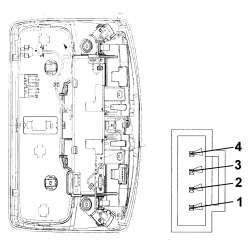
- Pin Out
| Pin | Function |
|---|---|
| 1 | + 30 |
| 2 | Earth |
| 3 | + 15 |
| 4 | A-BUS |
Parts & tools for this job Staging For 2005 Alfa Romeo Brera
- TOOLOBD2 scannerSearch: OBD2 scanner
- TOOLDigital multimeterSearch: automotive digital multimeter
- TOOLBack-probe test leadsSearch: back probe test leads
Links open Amazon search results in a new tab. As an Amazon Associate I earn from qualifying purchases.