
E3050 Front window mechanism (RH drive adaptation)
- Make
- Alfa Romeo
- Model
- 156 Factory Service Manual
- Year
- 1997–2002
- Section
- Electrical activation devices › E3050 Front window mechanism (RH drive adaptation)
E3050 Front window mechanism (RH drive adaptation)
Description
The electric front windows are operated automatically, depending on how the switch is pressed:
- for the driver's window:
- the operation is manual (the glass goes up/down only when the button is pressed) when the button is held down for 60 to 300 milliseconds;
- the operation is instead automatic (the glass continues to go up/down to the end of travel, even if the button is released) when the button is held down for over 300 milliseconds;
- if the button is pressed again during movement of the glass, the glass is stopped instantly;
- if the button is pressed for less than 60 milliseconds, it is ignored (it is considered to have been knocked accidentally).
- - for the passenger's window:
- closing is only manual;
- opening is the same as for the driver's window (automatic).
Both windows can only be operated when the ignition is on.
This operating logic is controlled by the integrated services control unit, on the left under the dashboard.
The control unit also carries out a series of safety checks:
- the stopping of the electric windows (switching off the electric supply to the motor) is determined when the glass reaches the end of travel at top or bottom, or if an obstacle blocks the glass. This is regulated by checking the motor current.
- if there are faults on the electrical circuits, the control unit switches the system off temporarily (for example if the motor control signals are interrupted or if the absorbed current is below the usual values);
- if there is a fault in the control buttons (short circuit, or buttons jammed in the pressed position), the control unit switches the system off temporarily
The control circuit for the front electric windows is protected by a specific fuse, in the junction unit. The operating buttons are also protected by the fuse which protects the other supplied controlled by the ignition.
The control switch symbols are lit when the key is turned to MAR.
Description of operation
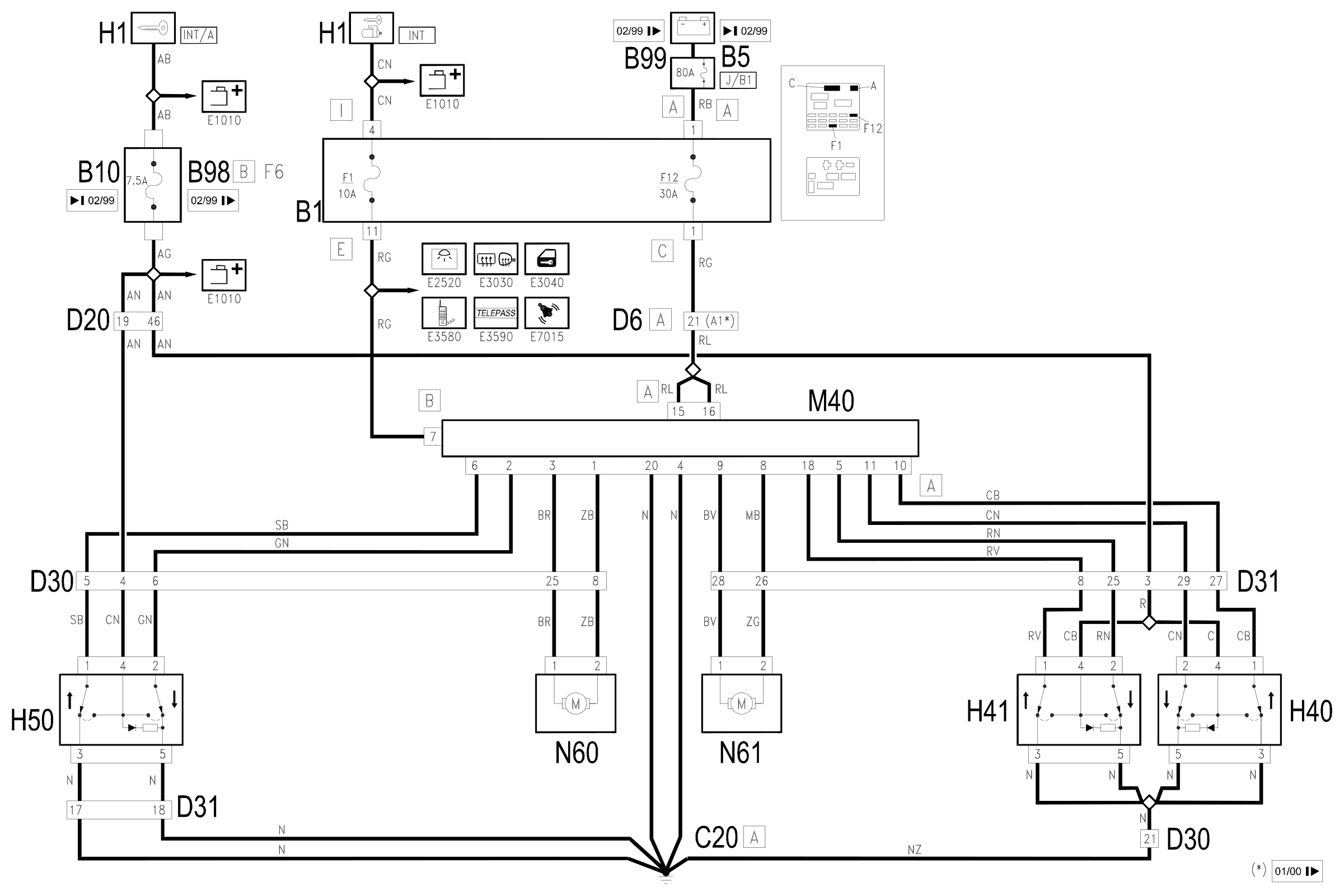
The integrated services control unit M40 manages the operation of the electric front windows.
The direct supply from the battery for control unit M40 specific to the electric windows (pin 15 and 16 of connector A) arrives from the line protected by maxifuse J/B1 (of B5 up to 2/99 or B99 from 2/99) and fuse F12 of junction unit B1, while the supply controlled by the ignition reaches pin 7 of connector B from the line for fuse F1; pins 4 and 20 of connector A provide the reference earth for the passenger and driver's electric windows, respectively. Pins 4 and 20 of connector A provide the reference earth for the passenger and driver electric windows, respectively.
The switches H40 (driver's electric window), H41 (passenger electric window on driver's door) and H50 (passenger electric windoe on passenger front door) receive a supply controlled by the ignition (INT/A) from the line from fuse B10 up to 2/99 or from fuse F6 of the additional fuse box B98B from 2/99, and are earthed C20: in this way they are also lit up when the ignition is switched on.
When the switches are operated, they send control signals (positive and negative) to control unit M40:
- at pins 10 and 11 of connector A from switch H40;
- at pins 5 and 18 of connector A from switch H41;
- at pins 2 and 6 of connector A from switch H50;
The control unit M40 operates the electric windows on the basis of the logic described previously:
- from pins 1 and 3 of connector A it sends commands to the driver's electric window motor N60.
- from pins 8 and 9 of connector A it sends commands to the passenger's electric window motor N61.
When the positive and negative signals are reversed, the motor direction of rotation is also reversed.
Wiring diagram
Components
| Code | Component | See |
|---|---|---|
| B01 | Junction unit | description 5505A |
| B05 | MAXI FUSE-1 box | |
| B10 | Key-dependent supply fuse (INT/A) | |
| B98 | Supplementary fuse box | description 5505A |
| B99 | Maxifuse box on battery | |
| C20 | Passenger side dashboard earth | description 5505A |
| D06 | Front / rear connection | |
| D20 | Dashboard/rear connection | |
| D30 | Rear / front door connection left | |
| D31 | Right front door rear coupling/. | |
| H01 | Ignition switch | description 5520A |
| H40 | Switch for front electric window on driver's door | description 7005M |
| H41 | Switch for passenger's electric window on driver's door | description 7005M |
| H50 | Electric window switch on passenger door | description 7005M |
| M40 | Integrated services control unit | description 5505A |
| N60 | Front left electric window motor | description 7005M |
| N61 | Front right electric window motor | description 7005M |
Component location
Parts & tools for this job Staging For 1997 Alfa Romeo 156
- TOOLTrim removal tool kitSearch: trim removal tool kit
- PARTTouch-up paintSearch: Alfa Romeo touch up paint
- PARTPanel clip assortmentSearch: Alfa Romeo panel clips assortment
Links open Amazon search results in a new tab. As an Amazon Associate I earn from qualifying purchases.