
E3032 External mirrors adjustment
- Make
- Alfa Romeo
- Model
- 156 Factory Service Manual
- Year
- 1997–2002
- Section
- Electrical activation devices › E3032 External mirrors adjustment
E3032 External mirrors adjustment
Description
The two external rear view mirrors are adjusted by the control on the central console between the seats, which is lit up when the side lights are on. The two mirrors are adjusted by a single button pressed in the four directions: a switch selects the right or left mirror.
The button, which can be pressed in four directions, controls two electric motors located in each of the two mirrors: one motor rotates the mirror on a horizontal axis, while the other on a vertical axis.
The adjustment circuit for the rear view mirrors is protected by the fuse which protects other supplies controlled by the ignition.
The mirrors can only be adjusted with the ignition switched ON.
Description of operation
The two-way switch controlling mirrors H30 operates electrical motors located in the right and left electrically-operated door mirrors P60 and P61 respectively.
The switch is supplied when the ignition is switched on (INT/A) at pin 2 of H30, by the line for fuse B10 up to 2/99 or fuse F6 of the additional fuse box B98B from 2/99; pin 4 is earthed. Pin 4 is earthed.
Operating the switch in one direction or the other, sends one of the two motors a positive and an earth signal, thereby determining the direction of rotation. The motors which adjust the vertical position are connected to pin 5 of the mirrors P60 and P61, the motors which adjust the horizontal position are connected to pin 3. According to the selector position, either the left motors (output signals from pins 6 and 8 of H30) or the right motors (output signals from pins 5 and 7 of H30) are connected; the common supply comes out of pin 3 and is connected to pin 5 of the motors. the common supply comes out of pin 3 and is connected to pin 5 of the motors.
The switch H30 is lit up when the side lights are switched on by means of the line coming from the stalk unit switch H5 (pin 1).
Wiring diagram
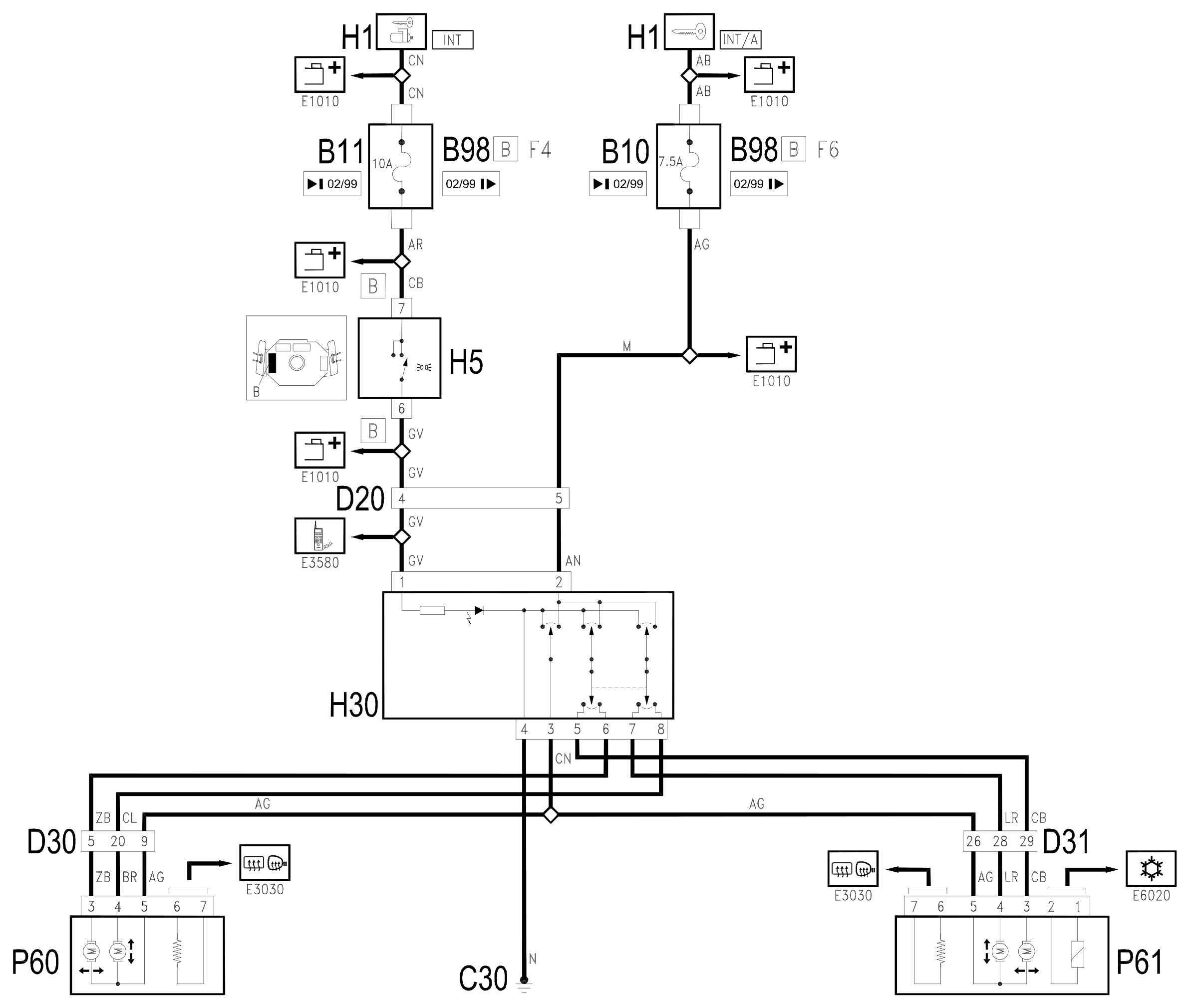
Components
| Code | Component | See |
|---|---|---|
| B10 | Key-dependent supply fuse (INT/A) | |
| B11 | Controls lighting fuse | |
| B98 | Supplementary fuse box | description 5505A |
| C30 | Left rear earth | description 5505A |
| D20 | Dashboard/rear connection | |
| D30 | Rear / front door connection left | |
| D31 | Right front door rear coupling/. | |
| H01 | Ignition switch | description 5520A |
| H05 | Steering column switch unit | description 5550A |
| H30 | Adjustable mirror control | description 7005R |
| P60 | Left door mirror | description 7005R |
| P61 | Right door mirror | description 7005R |
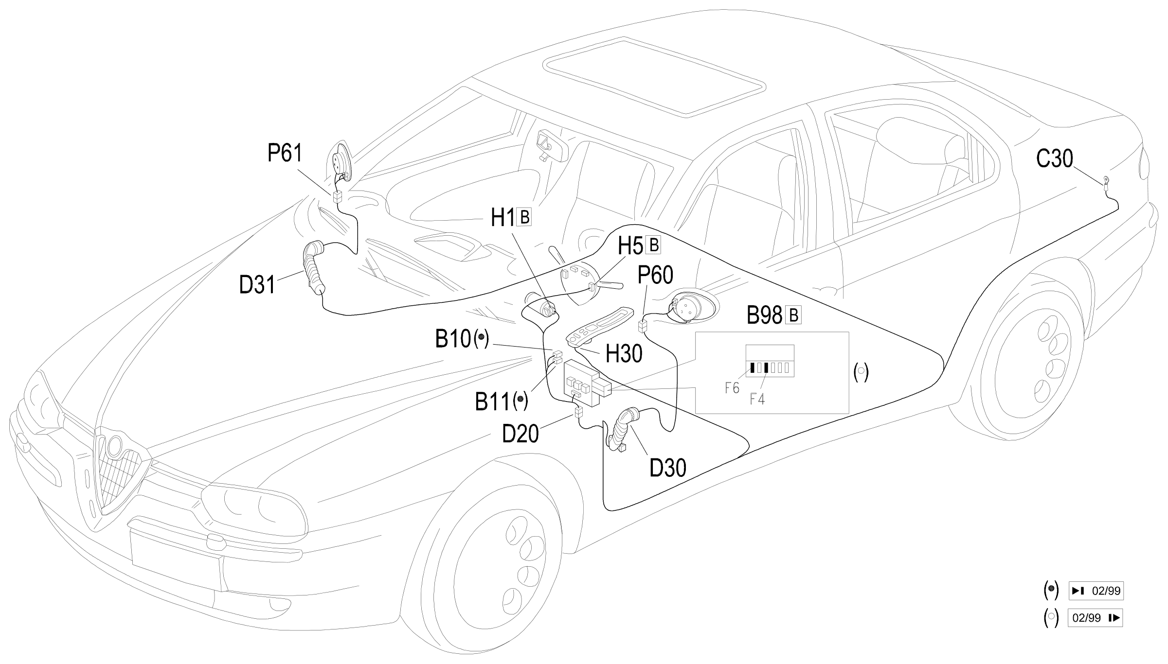
Component location
Parts & tools for this job Staging For 1997 Alfa Romeo 156
- TOOLTrim removal tool kitSearch: trim removal tool kit
- PARTTouch-up paintSearch: Alfa Romeo touch up paint
- PARTPanel clip assortmentSearch: Alfa Romeo panel clips assortment
Links open Amazon search results in a new tab. As an Amazon Associate I earn from qualifying purchases.