
Piston connecting rod set - r r
- Make
- Lancia
- Model
- Ypsilon Factory Service Manual
- Year
- 2003–2011
- Section
- Pistons and connecting rods › Piston connecting rod set - r r
Piston connecting rod set - r r
Removing
- 1020A24 crank case oil sump - r + r clean seals for sealant application with engine removed
1. Position the flywheel retainer.
| Name | Country | |
|---|---|---|
| 1 | Counter-torque | 1.860.846.000 |
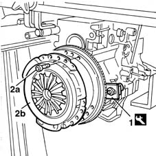
2. Undo the fixing bolts (2a) and remove the clutch plate (2b).
Removing
- 1020A24 crank case oil sump - r + r clean seals for sealant application with engine removed
1. Position the flywheel retainer.
| Name | Country | |
|---|---|---|
| 1 | Counter-torque | 1.860.846.000 |
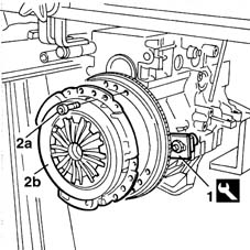
2. Undo the fixing bolts (2a) and remove the clutch plate (2b).
Removing
- 1020A24 crank case oil sump - r + r clean seals for sealant application with engine removed
1. Position the flywheel retainer.
| Name | Country | |
|---|---|---|
| 1 | Counter-torque | 1.860.846.000 |
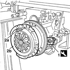
2. Undo the fixing bolts (2a) and remove the clutch plate (2b).
Removing
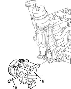
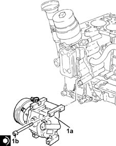
1. Undo the bolts (1a) and remove the air conditioning compressor (1b).
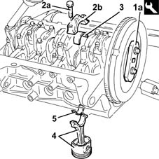
1. Remove the two bolts fixing the engine flywheel and position the tool (1a) for rotating the crankshaft.
| Name | Country | |
|---|---|---|
| 1a | Flange | 1.860.815.000 |
Remove the flywheel lock fitted previously.
Rotate the crankshaft using the tool fitted previously until cylinders no. 1 and no. 4 are at T.D.C
2. Undo the bolts (2a) and remove the connecting rod cap (2b) for cylinders 1 and 4.
3. Remove the lower connecting rod half bearings for cylinders no. 1 and no. 4.
4. Remove the connecting rod-piston assemblies for cylinders 1 and 4.
5. Remove the upper connecting rod half bearings for cylinders 1 and 4.
Proceed in the same way to remove the pistons and connecting rods for cylinders 2 and 3.
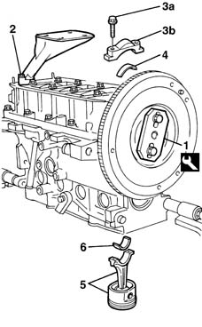
1. Remove the two bolts fixing the engine flywheel and position the tool (1a) for rotating the crankshaft.
| Name | Country | |
|---|---|---|
| 1 | Flange | 1.860.815.000 |
Remove the flywheel lock fitted previously.
2. Undo the bolts and remove the oil inlet from the oil pump.
Rotate the crankshaft using the tool fitted previously until cylinders no. 1 and no. 4 are at T.D.C
3. Undo the bolts (3a) and remove the big end bearing caps (3b) for cylinders no. 1 and no. 4.
4. Remove the lower connecting rod half bearings for cylinders no. 1 and no. 4.
5. Remove the connecting rod-piston assemblies for cylinders 1 and 4.
6. Remove the upper connecting rod half bearings for cylinders 1 and 4.
Proceed in the same way to remove the pistons and connecting rods for cylinders 2 and 3.
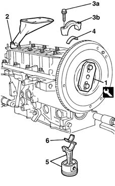
1. Remove the two bolts fixing the engine flywheel and position the tool (1a) for rotating the crankshaft.
| Name | Country | |
|---|---|---|
| 1 | Flange | 1.860.815.000 |
Remove the flywheel lock fitted previously.
2. Undo the bolts and remove the oil inlet from the oil pump.
Rotate the crankshaft using the tool fitted previously until cylinders no. 1 and no. 4 are at T.D.C
3. Undo the bolts (3a) and remove the big end bearing caps (3b) for cylinders no. 1 and no. 4.
4. Remove the lower connecting rod half bearings for cylinders no. 1 and no. 4.
5. Remove the connecting rod-piston assemblies for cylinders 1 and 4.
6. Remove the upper connecting rod half bearings for cylinders 1 and 4.
Proceed in the same way to remove the pistons and connecting rods for cylinders 2 and 3.
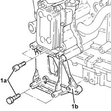
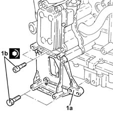
1. Undo the bolts (1a) and remove the air conditioning compressor support (1b).
Refitting
Rotate the crankshaft using the tool fitted previously.
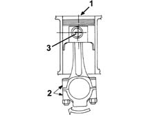
The connecting rod-piston assemblies are fitted with the references in the following positions.
1. Piston grade and arrow indicating the timing side.
2. Area where number of cylinder bore/liner to which the connecting rod belongs is stamped.
3. Connecting rod pin offset.
Refitting
Rotate the crankshaft using the tool fitted previously.
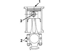
The connecting rod-piston assemblies are fitted with the references in the following positions.
1. Piston grade and arrow indicating the timing side.
2. Area where number of cylinder bore/liner to which the connecting rod belongs is stamped.
3. Connecting rod pin offset.
The letters for the cylinder bore/liner class are located on the cylinder block/crankcase.
Refitting
Rotate the crankshaft using the tool fitted previously.
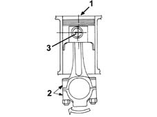
The connecting rod-piston assemblies are fitted with the references in the following positions.
1. Piston grade and arrow indicating the timing side.
2. Area where number of cylinder bore/liner to which the connecting rod belongs is stamped.
3. Connecting rod pin offset.
The letters for the cylinder bore/liner class are located on the cylinder block/crankcase.
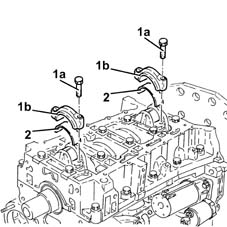
Rotate the engine through 180° on the overhauling stand.
1. Undo the bolts (1a) and remove the connecting rod caps (1b).
2. Remove the lower big end half-bearings.
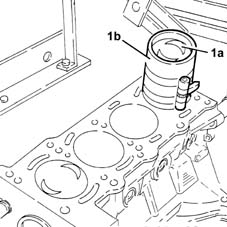
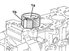
1. Fit the connecting rod-piston assemblies (1a), complete with half-bearings, using the tool (1b) for compressing the piston rings and later introducing the piston in the liner/bore.
| Name | Country | |
|---|---|---|
| 1b | Fitting tool | 1.860.700.000 |
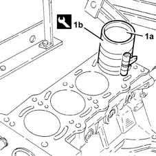
1. Fit the connecting rod-piston assemblies (1a), complete with half-bearings, using the tool (1b) for compressing the piston rings and later introducing the piston in the liner/bore.
| Name | Country | |
|---|---|---|
| 1b | Fitting tool | 1.860.700.000 |
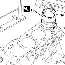
1. Fit the connecting rod-piston assemblies (1a), complete with half-bearings, using the tool (1b) for compressing the piston rings and later introducing the piston in the liner/bore.
| Name | Country | |
|---|---|---|
| 1b | Fitting tool | 1.860.700.000 |
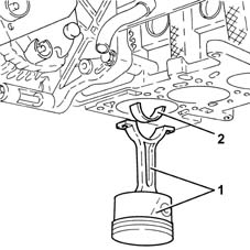
1. Remove the connecting rod-piston assemblies.
2. Remove the upper connecting rod half-bearings.
Rotate the engine on the overhauling stand.
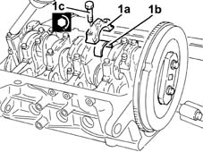
1. Fit the connecting rod caps (1a), complete with half-bearings (1b), and fix them tightening the bolts (1c) to the recommended torque.
The connecting rod caps are fitted so that the number stamped on them is facing the same side as the one stamped on the big end (inlet side).
| Fastening | Component | Ø | Value (daNm) | |
|---|---|---|---|---|
| 1c | Bolt | CONNECTING ROD CAP FASTENERS | M8 x 1 | 4.1 |
Rotate the engine on the overhauling stand.
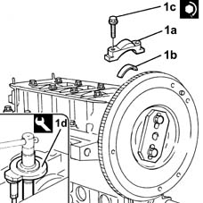
1. Fit the connecting rod caps (1a), complete with half-bearings (1b), and fix them tightening the bolts (1c) to the recommended torque using tool (1d) for the angular tightening.
The connecting rod caps are fitted so that the number stamped on them is facing the same side as the one stamped on the big end (inlet side).
| Fastening | Component | Ø | Value (daNm) | |
|---|---|---|---|---|
| 1c | Bolt | CONNECTING ROD CAP FASTENERS | M8 | 2 + 40° |
| Name | Country | |
|---|---|---|
| 1d | Protractor | 1.860.942.000 |
Rotate the engine on the overhauling stand.
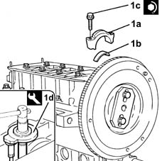
1. Fit the connecting rod caps (1a), complete with half-bearings (1b), and fix them tightening the bolts (1c) to the recommended torque using tool (1d) for angle tightening.
The connecting rods come with split caps. if replaced, they are supplied pre-split by the manufacturer. Check that the components are free of burrs, blisters, scratches or any type of surface defect. Before installation, the parts must be thoroughly washed, cleaned and dried. The connecting rod caps are fitted so that the number stamped on them is facing the same side as the one stamped on the big end (inlet side).
Each connecting rod must be matched with its own cap, respecting the printed reference numbers. connecting rods and connecting rod caps are not interchangeable.
| Fastening | Component | Ø | Value (daNm) | |
|---|---|---|---|---|
| 1c | Bolt | CONNECTING ROD CAP FASTENERS | M8 | 2 + 40° |
| Name | Country | |
|---|---|---|
| 1d | Protractor | 1.860.942.000 |
Refitting
Clean the components removed thoroughly and check their condition through a visual inspection.
Lubricate all the components for the mechanical couplings using engine oil.
Check the crankshaft bearings, taking into account that no adjustment operations should be carried out on half-bearings. If there are signs of grooves or seizing, they must be replaced.
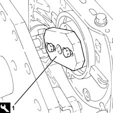
1. Fit the tool.
| Name | Country | |
|---|---|---|
| 1 | Flange | 1.860.815.000 |
Remove the tool for rotating the crankshaft.
| Name | Country | |
|---|---|---|
| Flange | 1.860.815.000 |
Fit the flywheel lock.
| Name | Country | |
|---|---|---|
| Counter-torque | 1.860.846.000 |
Fit the two bolts removed previously fixing the flywheel and tighten them to the recommended torque.
| Fastening | Component | Ø | Value (daNm) | |
|---|---|---|---|---|
| Bolt | FLYWHEEL | M8 x 1.25 | 4.4 |
1. Line up the driven plate for fitting the clutch assembly (1a), using the centring pin (1b).
| Name | Country | |
|---|---|---|
| 1b | Clutch centering | 1.870.418.000 |
2. Tighten the bolts fixing the clutch to the engine flywheel.
Remove the engine flywheel lock applied previously.
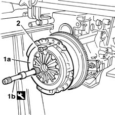
Remove the tool for rotating the crankshaft.
| Name | Country | |
|---|---|---|
| Flange | 1.860.815.000 |
Fit the intake on the oil pump.
Fit the flywheel lock.
| Name | Country | |
|---|---|---|
| 1 | Counter-torque | 1.860.846.000 |
Fit the two bolts removed previously fixing the flywheel and tighten them to the recommended torque.
| Fastening | Component | Ø | Value (daNm) | |
|---|---|---|---|---|
| 2c | Bolt | FLYWHEEL | M8 | 4.4 |
1. Line up the driven plate for fitting the clutch assembly (1a), using the centring pin (1b).
| Name | Country | |
|---|---|---|
| 1b | Clutch centering | 1.870.418.000 |
2. Tighten the bolts fixing the clutch to the engine flywheel.
Remove the engine flywheel lock applied previously.
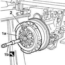
Remove the tool for rotating the crankshaft.
| Name | Country | |
|---|---|---|
| Flange | 1.860.815.000 |
Fit the intake on the oil pump.
Fit the flywheel lock.
| Name | Country | |
|---|---|---|
| Counter-torque | 1.860.846.000 |
Fit the two bolts removed previously fixing the flywheel and tighten them to the recommended torque.
| Fastening | Component | Ø | Value (daNm) | |
|---|---|---|---|---|
| Bolt | FLYWHEEL | M8 | 4.4 |
1. Line up the driven plate for fitting the clutch assembly (1a), using the centring pin (1b).
| Name | Country | |
|---|---|---|
| 1b | Clutch centering | 1.870.418.000 |
2. Tighten the bolts fixing the clutch to the engine flywheel.
Remove the engine flywheel lock applied previously.
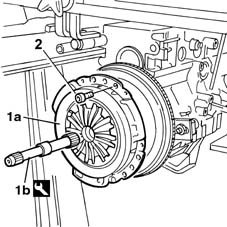
Rotate the crankshaft using the tool fitted previously.
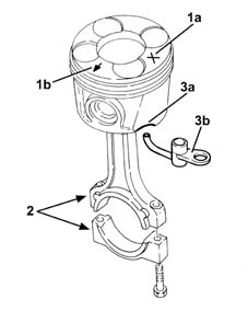
The piston-connecting rod assemblies are fitted according to the following references.
1. Piston category (1a) and arrow (1b) indicating timing side.
2. Area where number of cylinder bore/liner to which the connecting rod belongs is stamped.
3. Drain (3b) on the piston skirt must be aligned with oil spray (3b).
- 1020A24 crank case oil sump - r + r clean seals for sealant application with engine removed.
- 1020A24 crank case oil sump - r + r clean seals for sealant application with engine removed.
- 1020A24 crank case oil sump - r + r clean seals for sealant application with engine removed
1. Place the connecting rod-piston assemblies (1a) complete with upper connecting rod half-bearings using the tool (1b) back in their housings.
The big end bearing shells can be identified as follows:
- upper big end bearing shells, dark coloured three metal connecting rod side;
- lower big end bearing shells, light coloured two metal cap side with an opening.
Do not swap the position of the big end bearing shells.
Rotate the engine through 180° on the overhauling stand.
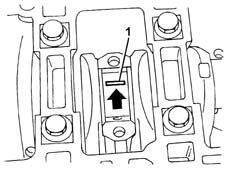
1. Fit the calibrated wire (Plastigage) to measure the big end bearing clearance.
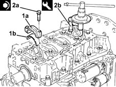
1. Place the big end caps (1a) complete with half-bearings (1b) back in their housings.
The big end bearing shells can be identified as follows:
- upper big end bearing shells, dark coloured three metal connecting rod side;
- lower big end bearing shells, light coloured two metal cap side with an opening.
Do not swap the position of the big end bearing shells.
2. Tighten the bolts (2a) fixing the connecting rod caps to the recommended torque using the angular tightening tool (2b).
| Fastening | Component | Ø | Value (daNm) | |
|---|---|---|---|---|
| 2a | Bolt | BIG END BEARING CAPS | M8 | 1.9 ÷ 2.1 + 40? ± 2? |
| Name | Country | |
|---|---|---|
| 2b | Protractor | 1.860.942.000 |
Undo the bolts and remove the connecting rod caps complete with half-bearings fitted previously.
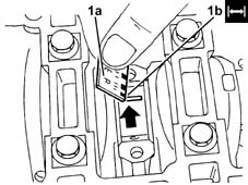
1. Using a suitable graduate measuring instrument (1a), measure the clearance shown by the calibrated wire (1b).
Check one journal at a time without moving the crankshaft.
| Measurement | Value | ||
|---|---|---|---|
| 1b | Big end bearings (mm) | 0.030 ÷ 0.062 |
If the reading is not within the specified range, replace the half-bearings with new ones of the appropriate size and grade.
Proceed with the final fitting of the connecting rod caps tightening the fixing bolts following the previous instructions.
Remove the tool.
| Name | Country | |
|---|---|---|
| Flange | 1.860.815.000 |
1. Place the air conditioning compressor mounting (1a) back in its housing and fix it tightening the bolts (1b) to the recommended torque.
| Fastening | Component | Ø | Value (daNm) | |
|---|---|---|---|---|
| 1b | Bolt | COMPRESSOR MOUNT (AC) | M8 | (Upper and lower engine crankcase side) 2.3 ÷ 2.8 |
1. Place the air conditioning compressor (1a) back in its housing and fix it tightening the bolts (1b) to the recommended torque.
| Fastening | Component | Ø | Value (daNm) | |
|---|---|---|---|---|
| 1b | Bolt | AIR CONDITIONER ASSEMBLY COMPRESSOR | M8 | (Support side) 2.3 ÷ 2.8 |
Parts & tools for this job Staging For 2003 Lancia Ypsilon
- PARTEngine gasket setSearch: Lancia Ypsilon 2003 engine gasket set
- TOOLTorque wrenchSearch: 3/8 inch torque wrench
- TOOLFeeler gauge setSearch: feeler gauge set
Links open Amazon search results in a new tab. As an Amazon Associate I earn from qualifying purchases.