
Fuel tank - r + r and decant fuel
- Make
- Lancia
- Model
- Ypsilon Factory Service Manual
- Year
- 2003–2011
- Section
- Fuel tank and pipes › Fuel tank - r + r and decant fuel
Fuel tank - r + r and decant fuel
Removing
Position the vehicle on the ramp.
Ensure that the ignition key is in OFF position, then disconnect the battery negative terminal (-).
| Name | Connector | |
|---|---|---|
| Battery | A1B |
Proceed with removal - 1040A70 submerged pump assembly complete with level guage control - r + r.
Drain the fuel from the tank using suitable equipment and appropriate protection to meet current safety requirements.
Proceed with removal - 7040L22 REAR TRIM on TUNNEL -R.R..
1. Slacken the handbrake cable adjustment nut.
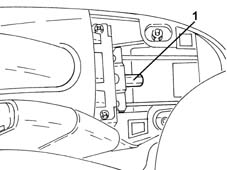
Removing
Position the vehicle on the ramp.
Ensure that the ignition key is in OFF position, then disconnect the battery negative terminal (-).
| Name | Connector | |
|---|---|---|
| Battery | A1B |
Proceed with removal - 1040A70 submerged pump assembly complete with level guage control - r + r.
Drain the fuel from the tank using suitable equipment and appropriate protection to meet current safety requirements.
Proceed with removal - 7040L22 REAR TRIM on TUNNEL -R.R..
1. Slacken the handbrake cable adjustment nut.
Removing
With the ignition key in the OFF position, disconnect the battery negative terminal.
Place the car on a ramp.
Drain the fuel from the tank using suitable equipment and appropriate protection to meet current safety requirements.
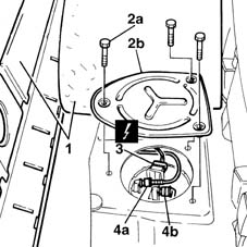
1. Lift the rear seat cushion lift the floor covering to gain access to the fuel pump flap.
2. Unscrew retaining bolts (2a) and remove protective cover (2b).
3. Disconnect the electrical connection from the fuel pump and level gauge.
| Name | Connector | |
|---|---|---|
| 3 | Fuel pump and sender unit | N40 |
4. Disconnect the fuel outlet and return lines from quick-release fittings (4a) and (4b).
Proceed with removal - 4450B08 right rear wheel r r.
Proceed with removal - 7055B45 right hand rear supplementary wheel arch - r+r.
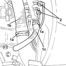
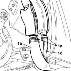
1. Open collars (1a) and disconnect fuel filler pipe (1b) and return pipe (1c).
2. Disconnect the rapid attachments for the fuel vapour recovery pipes from the float valves to the fuel vapour separator.
Proceed with removal - 4450B08 right rear wheel r r.
Proceed with removal - 7055B45 right hand rear supplementary wheel arch - r+r.
1. Open collars (1a) and disconnect fuel filler pipe (1b) and return pipe (1c).
2. Disconnect the rapid attachments for the fuel vapour recovery pipes from the float valves to the fuel vapour separator.
1. Loosen the handbrake adjustment nut.
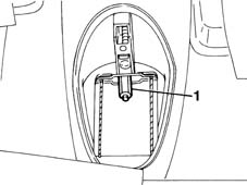
1. Undo bolt (1a) securing exhaust pipe support rear bracket.
2. Undo bolt (2a) securing front exhaust pipe bracket (2b).
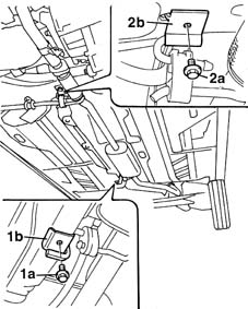
1. Undo bolt (1a) securing exhaust pipe support rear bracket.
2. Undo bolt (2a) securing front exhaust pipe bracket (2b).
1. Undo bolt (1a) securing exhaust pipe support rear bracket.
2. Undo bolt (2a) securing front exhaust pipe bracket (2b).
Raise the car.
1. Open collars (1a) and disconnect fuel filler pipe (1b) and vent pipe (1c).
1. Undo the fixing nuts (1a) and disconnect the exhaust pipe (1b) from the exhaust manifold with catalytic converter.
Move aside the exhaust pipe, securing it as appropriate to the bodyshell.
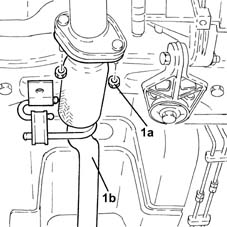
1. Undo the fixing nuts (1a) and disconnect the exhaust pipe (1b) from the exhaust manifold with catalytic converter.
Move aside the exhaust pipe, securing it as appropriate to the bodyshell.
1. Undo the fixing nuts (1a) and disconnect the exhaust pipe (1b) from the exhaust manifold with catalytic converter.
Move aside the exhaust pipe, securing it as appropriate to the bodyshell.
1. Undo the bolts fixing the exhaust pipe to the catalytic converter.
2. Undo the bolts and lower the exhaust pipe.
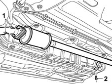
1. Release brake pipe (1a) from fastenings (1b) on the fuel tank.
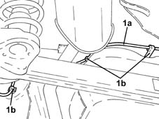
1. Undo the fixing nuts (1a) and disconnect the exhaust pipe (1b) from the exhaust manifold with catalytic converter.
1. Release brake pipe (1a) from fastenings (1b) on the fuel tank.
1. Open the band retaining the handbrake cable.
2. Undo retaining nuts (2a), remove the clip (2b) and remove the central heat shield (2c).
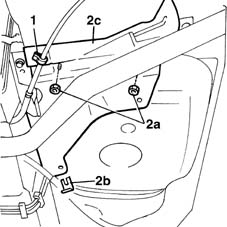
1. Open handbrake cable retaining cable.
2. Undo the nuts (2a), remove the clip (2b) and remove the central heat shield (2c).
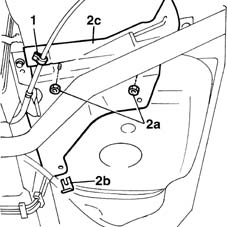
1. Open handbrake cable retaining cable.
2. Undo the nuts (2a), remove the clip (2b) and remove the central heat shield (2c).
1. Open handbrake cable retaining cable.
2. Undo the nuts (2a), remove the clip (2b) and remove the central heat shield (2c).
1. Remove protective cover (1a) and disconnect the handbrake cable from fitting (1b) on the shoes.
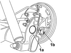
1. Remove the protective covers.
2. Disconnect the handbrake control cable from connection on the rear brake shoes.
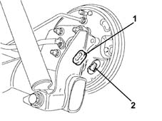
1. Remove the protective cover.
2. Disconnect the handbrake control cable from connection on the rear brake shoes.
1. Remove the protective covers.
2. Disconnect the handbrake control cable from connection on the rear brake shoes.
1. Position a stand supported by a hydraulic jack beneath the tank to support it during removal.
2. Undo the tank bracket retaining bolts.
3. Lower the hydraulic jack and remove the hydraulic tank.
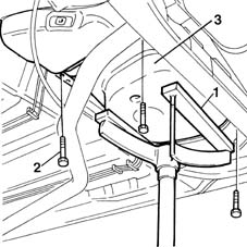
1. Place an appropriate stand under the fuel tank to support it during removal.
2. Undo the fuel tank bracket retaining bolts.
Lower the hydraulic jack and remove the fuel tank.
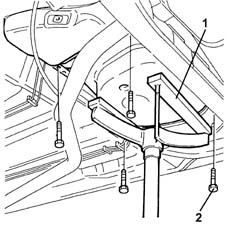
1. Place an appropriate stand under the fuel tank to support it during removal.
2. Undo the fuel tank bracket retaining bolts.
Lower the hydraulic jack and remove the fuel tank.
1. Place an appropriate stand under the fuel tank to support it during removal.
2. Undo the fuel tank bracket retaining bolts.
Lower the hydraulic jack and remove the fuel tank.
Refitting
Position the fuel tank on the stand.
Raise the tank until it fits into its seat.
Tighten the bolts securing the tank to the body.
Tighten the tank bolts to torque.
| Fastening | Component | Ø | Value (daNm) | |
|---|---|---|---|---|
| Bolt | FUEL TANK | M8 | 3.5 |
Remove the tank stand.
Connect the handbrake cable.
Fit the protective cap.
Fit the heat shield and secure it with its attachments.
Tighten the bolts securing the exhaust pipe to the catalytic converter and the bolts securing the ruber block to the bodyshell.
| Fastening | Component | Ø | Value (daNm) | |
|---|---|---|---|---|
| Bolt | EXHAUST PIPE TO ENGINE | M8 | (Catalytic converter) 2.5 |
Use new colllars to connect the fuel filler pipe.
Lower the vehicle.
Connect the fuel inlet and outlet pipe quick-release fittings.
Connect the electrical connection to the electric pump and level gauge.
Tighten the fuel pump protective cover retaining bolts.
Refit the floor covering.
Remove the vehicle from the lift.
Use the correct equipment and appropriate protection as required by current safety legislation to fill the vehicle with the recommended fuel.
- 3380A04 handbrake - check travel
With the ignition key in OFF position, connect the battery negative terminal.
Refitting
Place the fuel tank back in its housing using the hydraulic jack.
Tighten the bolts securing the fuel mounting brackets to the specified torque.
| Fastening | Component | Ø | Value (daNm) | |
|---|---|---|---|---|
| Bolt | FUEL TANK | M8 | (Bodyshell side) 3.2 ÷ 3.9 |
Remove the fuel tank support stand.
Connect the handbrake control cable to the fitting on the rear brake shoes.
Place the protective covers in their housings.
Refit the central heat shield in its seating, then secure it with the clip and nuts.
Secure the handbrake cables using the retaining band.
Secure the brake pipe using the fastenings on the fuel tank.
Refit the exhaust pipe, connect to the exhaust manifold with catalytic converter and tighten the nuts to the specified torque.
| Fastening | Component | Ø | Value (daNm) | |
|---|---|---|---|---|
| Nut | EXHAUST MANIFOLD WITH CATALYTIC CONVERTER | M8 | (Silencer side) 2.3 ÷ 2.8 |
Tighten the bolt securing the exhaust silencer front mounting bracket.
Undo exhaust pipe support front bracket securing bolts.
Connect the rapid attachments for the fuel vapour recovery pipes from the float valves to the fuel vapour separator.
Connect the fuel filler pipe and the return pipe. Secure using new bands.
Proceed with refitting - 7055B45 right hand rear supplementary wheel arch - r+r.
Proceed with refitting - 4450B08 right rear wheel r r.
Proceed with the refitting - 3380A04 handbrake - check travel
Proceed with refitting - 7040L22 REAR TRIM on TUNNEL -R.R..
Proceed with refitting - 1040A70 submerged pump assembly complete with level guage control - r + r.
Use the correct equipment and appropriate protection as required by current safety legislation to fill the vehicle with the recommended fuel.
Connect the negative (-) battery terminal.
Remove the car from the ramps.
Refitting
Place the fuel tank back in its housing using the hydraulic jack.
Tighten the bolts securing the fuel mounting brackets to the specified torque.
| Fastening | Component | Ø | Value (daNm) | |
|---|---|---|---|---|
| Bolt | FUEL TANK | M8 | (Bodyshell side) 3.2 ÷ 3.9 |
Remove the fuel tank support stand.
Connect the handbrake control cable to the fitting on the rear brake shoes.
Place the protective covers in their housings.
Refit the central heat shield in its seating, then secure it with the clip and nuts.
Secure the handbrake cables using the retaining band.
Secure the brake pipe using the fastenings on the fuel tank.
Refit the exhaust pipe, connect to the exhaust manifold with catalytic converter and tighten the nuts to the specified torque.
| Fastening | Component | Ø | Value (daNm) | |
|---|---|---|---|---|
| Nut | EXHAUST MANIFOLD WITH CATALYTIC CONVERTER | M8 | (Silencer side) 2.3 ÷ 2.8 |
Tighten the bolt securing the exhaust silencer front mounting bracket.
Tighten the bolt securing the exhaust silencer front mounting bracket.
Connect the rapid attachments for the fuel vapour recovery pipes from the float valves to the fuel vapour separator.
Connect the fuel filler pipe and the return pipe. Secure using new bands.
Proceed with refitting - 7055B45 right hand rear supplementary wheel arch - r+r.
Proceed with refitting - 4450B08 right rear wheel r r.
Proceed with the refitting - 3380A04 handbrake - check travel
Proceed with refitting - 7040L22 REAR TRIM on TUNNEL -R.R..
Proceed with refitting - 1040A70 submerged pump assembly complete with level guage control - r + r.
Use the correct equipment and appropriate protection as required by current safety legislation to fill the vehicle with the recommended fuel.
Connect the negative (-) battery terminal.
Remove the car from the ramps.
Parts & tools for this job Staging For 2003 Lancia Ypsilon
- PARTEngine gasket setSearch: Lancia Ypsilon 2003 engine gasket set
- TOOLTorque wrenchSearch: 3/8 inch torque wrench
- TOOLFeeler gauge setSearch: feeler gauge set
Links open Amazon search results in a new tab. As an Amazon Associate I earn from qualifying purchases.