
Single cylinder head, removed - overhaul
- Make
- Fiat
- Model
- Panda Factory Service Manual
- Year
- 2003–2012
- Section
- Cylinder head/s › Single cylinder head, removed - overhaul
Single cylinder head, removed - overhaul
Dismantling
- 1036B14 overhead camshaft - r r on vehicle - with cylinder head removed
1. Remove the camshaft tappet cases with shims.
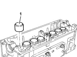
Dismantling
Carry out op. 1036B14
1. Remove the camshaft tappet cases with shims.
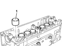
Dismantling
UPPER CYLINDER HEAD
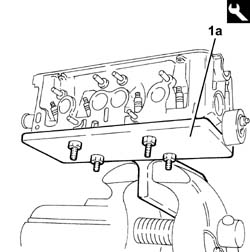
1. Position the upper cylinder head (1a) in the vice using the tool (1b).
| Name | Country | |
|---|---|---|
| 1b | Mount | 1.860.470.001 |
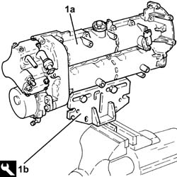
1. Fit the valve retainer beneath the cylinder head.
| Name | Country | |
|---|---|---|
| 1 | Stand | 1.860.749.000 |
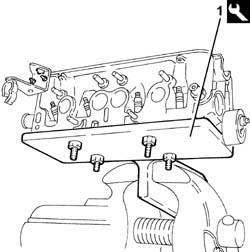
1. Fit valve retainer (1a) beneath the cylinder head.
| Name | Country | |
|---|---|---|
| 1a | Stand | 1.860.749.000 |
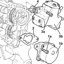
1. Undo bolts (1a) and remove vacuum unit (1b).
2. Remove the gasket.
3. Undo the bolts (3a) and remove the pressure pump (3b) complette with O-Ring.
4. Remove the coupling.
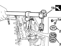
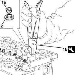
1. Remove cotters (1a) using tool (1b).
| Name | Country | |
|---|---|---|
| 1b | Tool | 1.860.644.000 |
2. Remove the upper valve shims.
3. Remove the valve springs.
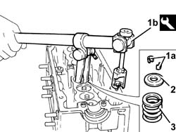
1. Remove cotters (1a) using tool (1b).
2. Remove the upper valve shims.
3. Remove the valve springs.
| Name | Country | |
|---|---|---|
| 1b | Tool | 1.860.644.000 |
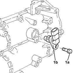
1. Undo the bolts (1a) and remove the cam angle sensor (1b).
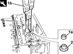
1. Remove the valve guide oil seals (1a) using the tool (1b).
| Name | Country | |
|---|---|---|
| 1b | Extractor | 1.860.989.000 |
2. Remove the lower valve shims.
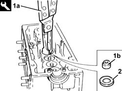
1. Using pliers (1a), remove the oil seals (1b) from the valve guides.
2. Remove the lower valve shims.
| Name | Country | |
|---|---|---|
| 1a | Extractor | 1.860.989.000 |
Temporarily remove the tool fitted previously on the exhaust side camshaft.
| Name | Country | |
|---|---|---|
| Gauge | 1.870.896.900 |
Check that the end float of the camshaft is within the recommended values using a dial gauge.
| Measurement | Value | ||
|---|---|---|---|
| End float (mm) | 0.15 ÷ 0.34 |
If the end float of the camshaft is not within the recommended values, when reassembling the cylinder head, replace the worn components.
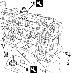
1. Remove the plug (1a) and fit the tool (1b) on the inlet side camshaft.
Fit the tool positioning it with the references in a horizontal direction and checking that it is correctly inserted in the housing in the camshaft.
| Name | Country | |
|---|---|---|
| 1b | Gauge | 1.870.896.900 |
2. Undo the camshaft sprocket fixing bolts.
Remove the valve retaining tool fitted previously and remove the valves.
| Name | Country | |
|---|---|---|
| Stand | 1.860.749.000 |
1. Undo the nut (1a) and remove the moving timing drive belt tensioner (1b).
2. Remve the engine coolant temperature sender unit
| Name | Connector | |
|---|---|---|
| 2 | Engine coolant temperature sensor/sender unit | K36 |
3. Remove the spark plugs.
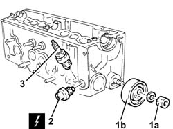
Remove the valve retaining tool fitted previously and remove the valves.
| Name | Country | |
|---|---|---|
| Stand | 1.860.749.000 |
1. Undo the nut (1a) and remove the mobile timing drive belt tensioner (1b).
2. Remove the spark plugs.
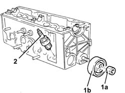
1. Remove the camshaft timing tools from the camshaft housing.
| Name | Country | |
|---|---|---|
| 1 | Gauge | 1.870.896.900 |
2. Release the camshafts (2a) as necessary and remove the camshaft gears (2b).
Remove the camshafts completely.
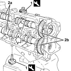
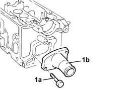
1. Undo the bolts (1a) and remove the thermostat (1b) with gasket.
2. Undo the attachments and remove the cable mount bracket.
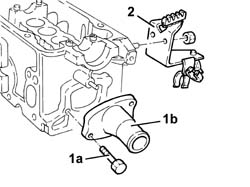
1. Undo the bolts (1a) and remove the thermostat (1b) with gasket.
Remove the support tool, complete with upper cylinder head from the vice and separate them.
CYLINDER HEAD
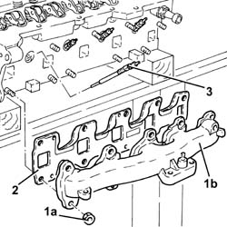
1. Undo the nuts (1a) and remove the exhaust manifold (1b).
2. Remove the exhaust manifold gasket.
3. Undo and remove the heater plugs.
Reassembling
Descale and clean the valve seats and ducts.
Clean the residues of the old gasket from the lower surface of the cylinder head.
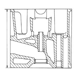
If necessary, reface the lower cylinder head surface without exceeding the minimum permitted cylinder head height.
| Measurement | Value | ||
|---|---|---|---|
| Permissible minimum height (mm) | 125.35 |
Reassembling
De-carbonize and clean the valve seats and ducts.
Clean the residues of the old gasket from the lower surface of the cylinder head.
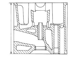
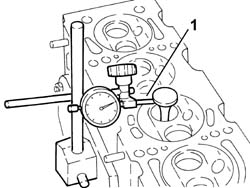
Check cylinder head planarity and level the lower cylinder head surface if necessary; it is permissible to remove 0.1 mm of material over and above the minimum cylinder head height (factory dimension).
| Measurement | Value | ||
|---|---|---|---|
| Cylinder head height (construction figure) (mm) | 126.5 +/- 0.35 |
1. Position the cylinder head (1a) in the vice using the tool (1b).
| Name | Country | |
|---|---|---|
| 1b | Mount | 1.860.470.001 |
2. Remove the valve rocker arms.
3. Remove the hydraulic tappets.
4. Remove the camshaft housing centring bushes.
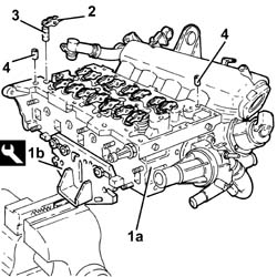
After levelling, check that combustion chamber volume is with specified limits by fitting the valves and spark plugs provisionally.
| Measurement | Value | ||
|---|---|---|---|
| Combustion chamber volume (cm) | 23.41 |
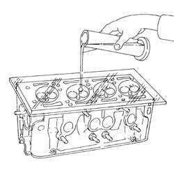
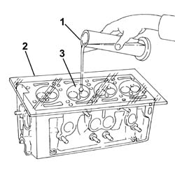
After levelling, check that combustion chamber volume is with specified limits as follows.
1. Fit valves and spark plugs provisionally. Take a graduated burette containing a known amount of engine oil.
2. Rest a glass sheet with four holes corresponding to the combustion chambers on the cylinder head.
3. Complete the filling of the combustion chamber, taking care that no oil comes out of the combustion chamber.
Wait for around 10 minutes to allow the decantation of the oil.
Measure the quantity of oil remaining in the burette and then calculate the difference between it and the quantity of oil used initially when the burette was full; this value corresponds to the volume of the chamber.
Check that this figure corresponds to the recommended values, or else the cylinder head has to be replaced.
| Measurement | Value | ||
|---|---|---|---|
| Combustion chamber volume (cm) | 23.41 |
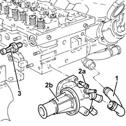
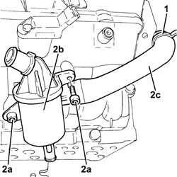
1. Loosen the bands and remove the coolant supply hose from the thermostat to the E.G.R. system exhaust gas/water heat exchanger.
2. Undo the bolts (2a) and remove the thermostat (2b) complete with O-Ring.
3. Undo and remove the engine oil pressure warning light switch.
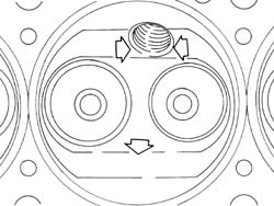
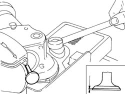
If combustion chamber volume is not as specified, remove material from the arrowed points.
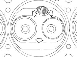
If combustion chamber volume is not as specified, remove material from the arrowed points.
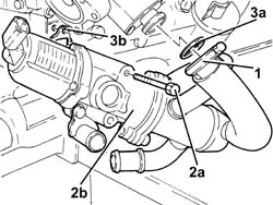
1. Loosen the collar fixing the E.G.R. system exhaust gas/coolant heat exchanger, air chamber side.
2. Undo the bolt (2a) and remove the E.G.R. system exhaust gas/heat exchanger assembly (2b).
3. Remove the gaskets (3a) and (3b).
Check that the valve stem does not show signs of scoring or seizing.
Check that the diameter of the valve stems is within the recommended values; if this is not the case, replace the worn valves.
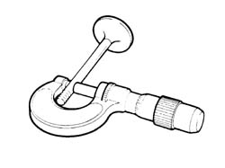
Check that the valve stem does not show signs of scoring or seizing.
Check that the diameter of the valve stems is within the recommended values; if this is not the case, replace the worn valves.
| Measurement | Value | ||
|---|---|---|---|
| Inlet and exhaust valve stem diameter (mm) | 6.982 - 7.000 |
Check that the thickness of the cylindrical part of the valve head is within the recommended values.
| Measurement | Value | ||
|---|---|---|---|
| Valve cylindrical section thickness (mm) | 1 |
Check that the diameter of the valve head is within the recommended values; if this is not the case, replace the valves.
| Measurement | Value | ||
|---|---|---|---|
| Inlet valve external diameter (mm) | 31.20 - 31.50 |
| Measurement | Value | ||
|---|---|---|---|
| Exhaust valve external diameter (mm) | 27.20 - 27.50 |
1. Check valve guide bore and valve clearance are within the recommended values or else the valve guide has to be replaced.
If necessary, replace the valve guides referring to op. 1016E14.
| Measurement | Value | ||
|---|---|---|---|
| Valve guide inner diameter (mm) | 7.022 - 7.040 |
| Measurement | Value | ||
|---|---|---|---|
| Valve stem - valve guide diameter (mm) | 0.022 - 0.058 |
1. Release the engine oil vapour recirculation pipe from the fastening band on the air chamber.
2. Undo the bolts (2a) and remove the engine oil vapour separator (2b) complete with engine oil vapour recirculation pipe (2c).
If necessary, grind the valves to an angle of 45° 30' 5'
| Measurement | Value | ||
|---|---|---|---|
| Stem diameter (mm) | 6.982 - 7.000 |
If necessary, grind the valve stem surface, removing as little material as possible.
Check that the thickness of the cylindrical part of the valve head is within the recommended values.
| Measurement | Value | ||
|---|---|---|---|
| Thickness of valve head cylindrical section (mm) | 1 |
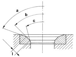
Grind the valve seats if the valves and valve guides are replaced.
| Measurement | Value | ||
|---|---|---|---|
| Upper section taper "" (-) | 75° |
| Measurement | Value | ||
|---|---|---|---|
| Contact band with valve taper "b" (-) | 44° 30' |
| Measurement | Value | ||
|---|---|---|---|
| Lower band taper"c" (-) | 20° |
| Measurement | Value | ||
|---|---|---|---|
| Contact band width with valve "I" (mm) | c.a. 2 |
Clean the valve seats thoroughly when the operation is complete.
1. Undo the bolts (1a) and remove the air chamber (1b) complete with excess pressure sensor.
2. Remove the gasket.
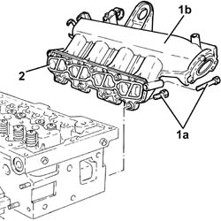
Check that the endfloat between the valve steam and seats is within the specified values; if this is not the case, replace the worn parts (for valve guide replacement, see op. 1016E14).
| Measurement | Value | ||
|---|---|---|---|
| Stem radial clearance (mm) | 0.022 - 0.058 |
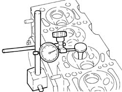
Use the appropriate tool to check that the characteristics of the springs are within the recommended values; if this is not the case, replace parts that have yielded.
| Measurement | Value | ||
|---|---|---|---|
| Spring height (mm) | 31 | ||
| Under load (daN) | 21.2 - 23.8 | ||
| Measurement | Value | ||
|---|---|---|---|
| Spring height (mm) | 21.5 | ||
| Under load (daN) | 61.4 - 65.5 | ||
Check that the diameter of the camshaft journals is within the recommended values; if this is not the case, replace the worn camshaft.
| Measurement | Value | ||
|---|---|---|---|
| Side bearing diameter (mm) | 24.000 - 24.015 |
| Measurement | Value | ||
|---|---|---|---|
| Centre bearing diameter (mm) | 23.500 - 23.515 |
Check that the nominal lift of the camshaft cams is within the recommended values; if this is not the case, replace the worn camshat.
| Measurement | Value | ||
|---|---|---|---|
| Nominal cam lift (mm) | 9.5 |
Check that the diameter of the camshaft tappet casing housings are within the recommended values; if this is not the case, replace the worn parts.
| Measurement | Value | ||
|---|---|---|---|
| Outer diameter (mm) | 34.975 - 34.995 |
Check that the diameter of the camshaft tappet casing housings are within the recommended values; If this is not the case, replace the cylinder head.
| Measurement | Value | ||
|---|---|---|---|
| Tappet casing housing diameter (mm) | 35.000 - 35.025 |
Fit the thermostat, complete with a new gasket, and fix it tightening the bolts to the recommended torque.
| Fastening | Component | Ø | Value (daNm) | |
|---|---|---|---|---|
| Bolt | THERMOSTAT | M6 x 1 | 1 |
Fit the spark plugs and tighten them to the recommended torque.
| Fastening | Component | Ø | Value (daNm) | |
|---|---|---|---|---|
| SPARK PLUGS | M14 x 1.5 | 2.7 |
Fit the timing moving tensioner and fix it using the nut without tightening it.
1. Fit flywheel retaining tool (1a) after positioning the valves in their seats.
| Name | Country | |
|---|---|---|
| 1a | Stand | 1.860.749.000 |
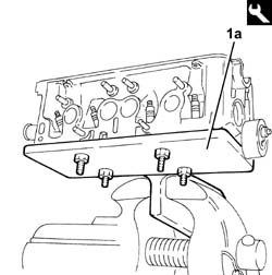
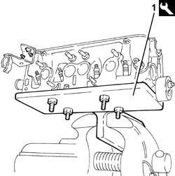
1. Place a wooden board on the cylinder head surface to support the valves and bolt in place.
| Name | Country | |
|---|---|---|
| 1 | Stand | 1.860.749.000 |
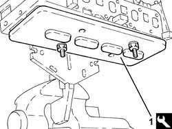
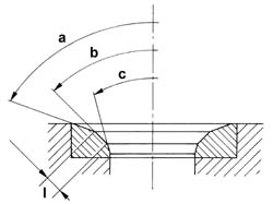
Grind the valve seats if the valves and valve guides are replaced.
| Measurement | Value | ||
|---|---|---|---|
| Upper section taper (mm) | "to" | 70° |
| Measurement | Value | ||
|---|---|---|---|
| Valve contact band taper (mm) | "b" | 45° +\- 5' |
| Measurement | Value | ||
|---|---|---|---|
| Lower band taper (mm) | "c" | 15° |
| Measurement | Value | ||
|---|---|---|---|
| Valve contact band width (mm) | " l " | +\- 2 |
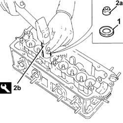
1. Fit the lower valve shim.
2. Fit the valve guide oil seal (2a) using tool (2b).
| Name | Country | |
|---|---|---|
| 2b | Fitting tool | 1.860.313.000 |
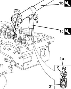
1. Remove the cotters (1a) using tools (1b) and (1c).
| Name | Country | |
|---|---|---|
| 1b | Lever | 1.860.644.001 |
| Name | Country | |
|---|---|---|
| 1c | Chamber | 1.870.881.000 |
2. Remove the upper valve shim.
3. Remove the valve spring.
Detect the valve abutment line in the seats. If the contact is not centred, repeat the valve guide grinding operation.
Dress the valves in their seats after spreading the contact surfaces with abrasive paste and using a special tool wtih sucker.
Clean the valves and valve seats thoroughly when the operation is complete.
Use a torque wrench to check that the valve spring specifications are within specified values; if this is not the case, replace parts that have yielded.
| Measurement | Value | ||
|---|---|---|---|
| Length under load (mm) | 32.1 | ||
| Laden (daN) | 18.74 ÷ 21.34 | ||
| Measurement | Value | ||
|---|---|---|---|
| Length under load (mm) | 22.6 | ||
| Laden (daNm) | 58.40 ÷ 62.60 | ||
Check that the diameter of the camshaft journals is within the recommended values; if this is not the case, replace the worn camshaft.
| Measurement | Value | ||
|---|---|---|---|
| Side bearing diameter (mm) | 24.000 - 24.015 |
| Measurement | Value | ||
|---|---|---|---|
| Centre bearing diameter (mm) | 23.500 - 23.515 |
Check that the nominal lift of the camshaft cams is within the recommended values; if this is not the case, replace the worn camshat.
| Measurement | Value | ||
|---|---|---|---|
| Nominal cam lift (mm) | 8.8 |
Check that the diameter of the camshaft tappet casing housings are within the recommended values; if this is not the case, replace the worn parts.
| Measurement | Value | ||
|---|---|---|---|
| Tappet case external diameter (mm) | 34.975 - 34.995 |
Check that the diameter of the camshaft tappet casing housings are within the recommended values; If this is not the case, replace the cylinder head.
| Measurement | Value | ||
|---|---|---|---|
| Tappet casing housing diameter (mm) | 35.000 - 35.025 |
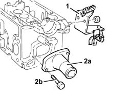
1. Fit the cable bracket and secure.
2. Fit the thermostat (2a), complete with a new gasket, and fix it tightening the bolts to the recommended torque.
Refit the valve springs, upper valve shims and cotters using the same tools as used for the dismantling.
| Name | Country | |
|---|---|---|
| Tool | 1.860.644.000 |
Remove the valve retainer removed previously.
| Name | Country | |
|---|---|---|
| Stand | 1.860.749.000 |
Fit the camshaft tappet cases with shims.
- 1036B14 overhead camshaft - r r on vehicle - with cylinder head removed
Work in the same way on the remaining valves.
Remove the wooden board and recover the valves.
| Name | Country | |
|---|---|---|
| Stand | 1.860.749.000 |
1. Remove the valve guide oil seals (1a) using the tool (1b).
| Name | Country | |
|---|---|---|
| 1b | Pliers | 1.870.894.000 |
2. Remove the lower valve shims.
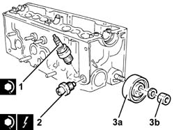
1. Fit the spark plugs and tighten them to the recommended torque.
| Fastening | Component | Ø | Value (daNm) | |
|---|---|---|---|---|
| 1 | SPARK PLUGS | M14 | 3.7 |
2. Fit the engine coolant temperature sending unit and tighten it to the recommended torque.
| Name | Connector | |
|---|---|---|
| 2 | Engine coolant temperature sensor/sender unit | K36 |
| Fastening | Component | Ø | Value (daNm) | |
|---|---|---|---|---|
| 2 | COOLANT TEMP GAUGE SENDING UNIT | M14 | 2.5 |
3. Fit the timing belt moving tensioner (3a) and fix it tightening the bolt (3b) to the recommended torque.
Remove the cylinder head from the support tool.
| Name | Country | |
|---|---|---|
| Support | 1.860.470.000 |
Replace the valve guides - 1016E14 single cylinder head valve guides - replace during operation 1016e10.
1. Fit the flywheel retaining tool after positioning the valves in their seats.
| Name | Country | |
|---|---|---|
| 1 | Stand | 1.860.749.000 |
Reassembling
Clean the residues of the old gasket from the lower surface of the cylinder head.
Clean the residues of the old gasket from the matching surfaces between the cylinder head and the camshaft housing.
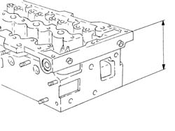
Check that the planarity of the lower cylinder head surface is within the recommended values.
| Measurement | Value | ||
|---|---|---|---|
| Flatness of bottom surface (mm) | 0.1 |
If the planarity of the lower cylinder head surface is not within the recommended values, regrind it starting from the nominal height of the head and, at the end of the operation, positioning a new gasket with the number of references indicated below.
The head can be reground by 0.1 mm if starting with a gasket with 0 references and using a new gasket with 1 reference.
The head can be reground by 0.2 mm if starting with a gasket with 0 references and using a new gasket with 2 references.
The head can be reground by 0.1 mm if starting with a gasket with 1 reference and using a new gasket with 2 references.
If the limit condition is reached (head gasket with 2 references before regrinding), the cylinder head lower plane cannot be reground.
| Measurement | Value | ||
|---|---|---|---|
| Nominal lift (mm) | 105.5 ± 0.05 |
1. Fit the lower valve shim.
2. Fit the valve guide oil seal (2a) using tool (2b).
| Name | Country | |
|---|---|---|
| 2b | Fitting tool | 1.860.454.000 |
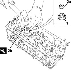
Check that the valves do not show signs of scoring or seizing.
Check that the diameter of the valve stems is within the recommended values; if this is not the case, replace the worn valves.
| Measurement | Value | ||
|---|---|---|---|
| Stem diameter, Inlet/Exhaust (mm) | 5.90 ÷ 5.94 |
Check that the length of the uncompressed valve springs is within the recommended values.
| Measurement | Value | ||
|---|---|---|---|
| Free length (mm) | 37.9 |
Use a torque wrench to check that the valve spring specifications are within specified values; if this is not the case, replace parts that have yielded.
| Measurement | Value | ||
|---|---|---|---|
| Length (mm) | 31.0 | ||
| under load (daN) | 16.2 ÷ 18.0 | ||
| Measurement | Value | ||
|---|---|---|---|
| Length (mm) | 23.5 | ||
| under load (daN) | 36.1 ÷ 39.5 | ||
Check that the cam journal diameters are within the recommended values; if this is not the case, replace the worn camshaft(s).
| Measurement | Value | ||
|---|---|---|---|
| Journal diameter (mm) | First pin | 38.500 ÷ 38.515 | |
| Second pin | 38.000 ÷ 38.015 | ||
| Third pin | 30.000 ÷ 30.015 | ||
Check that the nominal lift of the camshaft cams is within the recommended values; if this is not the case, replace the worn camshaft(s).
| Measurement | Value | ||
|---|---|---|---|
| Nominal cam lift (mm) | Exhaust | 7.5 | |
| Inlet | 6.4 | ||
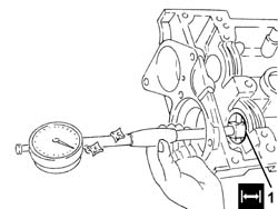
1. Check the diameter of the camshaft mounts is within specified values; If this is not the case, replace the cylinder head.
| Measurement | Value | ||
|---|---|---|---|
| 1 | Support diameter (mm) | First support | 38.545 ÷ 38.570 |
| Second support | 38.045 ÷ 38.070 | ||
| Third support | 30.045 ÷ 30.070 | ||
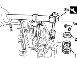
1. Fit the valve springs.
2. Fit the upper valve shims.
3. Fit cotters (3a) using tool (3b).
| Name | Country | |
|---|---|---|
| 3b | Tool | 1.860.644.000 |
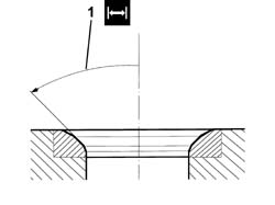
1. Regrind the valve seats to the recommended dimension.
| Measurement | Value | ||
|---|---|---|---|
| 1 | Contact band angle with valve (-) | 45° ± 20' |
Remove the valve retainer removed previously.
| Name | Country | |
|---|---|---|
| Stand | 1.860.749.000 |
Fit the camshaft tappet cases with shims.
- 1036B14 overhead camshaft - r r on vehicle - with cylinder head removed
Grind the valve seats using a suitable tool.
CYLINDER HEAD
Position the cylinder head in the vice using the tool.
| Name | Country | |
|---|---|---|
| Mount | 1.860.470.001 |
Fit the valves in their seats, then support them using the wooden board and secure them using bolts.
| Name | Country | |
|---|---|---|
| Stand | 1.860.749.000 |
Fit the lower valve shims back in their housings.
1. Fit the valve guide oil seals (1a) in their seats manually using the tool (1b).
| Name | Country | |
|---|---|---|
| 1b | Drift | 1.870.900.800 |
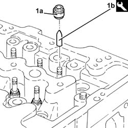
1. Place the valve spring back in its housing.
2. Place the upper valve shim back in its housing.
3. Place the split cotters (3a) back in their housings using the tools (3b) and (3c).
| Name | Country | |
|---|---|---|
| 3b | Lever | 1.860.644.001 |
| Name | Country | |
|---|---|---|
| 3c | Chamber | 1.870.881.000 |
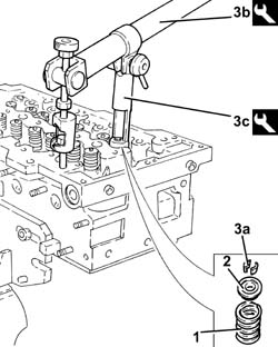
Work in the same way on the remaining valves.
Remove the wooden board for supporting the valves from the cylinder head plane.
| Name | Country | |
|---|---|---|
| Stand | 1.860.749.000 |
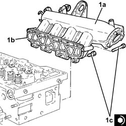
1. Place the air chamber (1a), complete with gasket (1b) and excess pressure sensor, back in its housing and secure it tightening the bolts (1c) to the recommended torque.
| Fastening | Component | Ø | Value (daNm) | |
|---|---|---|---|---|
| 1c | Bolt | INLET AIR DUCT | M8 | (Cylinder head side) 2.3 ÷ 2.8 |
Place the engine oil vapour separator, complete with engine oil recirculation pipes, back in its housing and fix it using the bolts.
Fasten the engine oil vapour recirculation pipe to the band on the air chamber.
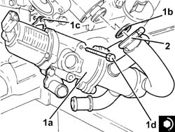
1. Place the E.G.R. system exhaust gas/water heat exchanger (1a) back in its housing complete with gaskets (1b) and (1c), then secure it tightening the bolts (1d) to the recommended torque.
| Fastening | Component | Ø | Value (daNm) | |
|---|---|---|---|---|
| 1d | Bolt | E.G.R EXHAUST GAS HEAT EXCHANGER. | M8 | (Cylinder head side) 2.0 ÷ 2.4 |
2. Tighten the collar fixing the E.G.R. system exhaust gas/water heat exchanger, air chamber side.
1. Fit the engine oil pressure warning light switch in its seating and tighten it to the recommended torque.
| Fastening | Component | Ø | Value (daNm) | |
|---|---|---|---|---|
| 1 | OIL PRESSURE W/L | M14 | (Cylinder head side) 2.9 ÷ 3.5 |
2. Refit the thermostat (2a), complete with O-ring, back in its housing and tighten the bolts (2b) to the specified torque.
| Fastening | Component | Ø | Value (daNm) | |
|---|---|---|---|---|
| 2b | Bolt | THERMOSTAT | M8 | (Cylinder head side) 2.3 ÷ 2.8 |
3. Refit the coolant supply hose between the thermostat and the E.G.R. system exhaust gas/water heat exchanger and secure it using the bands.
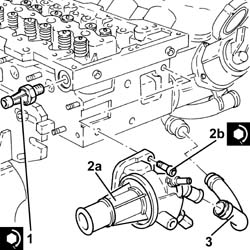
Place the camshaft housing centering bushes back in their seats.
Place the hydraulic tappets in their housings.
Position the hydraulic tappets with the oil port facing the outside of the cylinder head: this position places the above mentioned port in contact with the oil duct in the lower cylinder head.
Place the valve rocker arms back in their housings.
Remove the cylinder head from the support tool.
| Name | Country | |
|---|---|---|
| Mount | 1.860.470.001 |
1. Place the heater plugs back in their housings and tighten them to the recommended torque.
| Fastening | Component | Ø | Value (daNm) | |
|---|---|---|---|---|
| 1 | GLOW PLUGS | M8 | (Cylinder head side) 0.9 ÷ 1.0 |
2. Place an exhaust manifold gasket in the housing.
3. Place the exhaust manifold (3a) back in its housing and fix it tightening the nuts (3b) to the recommended torque.
| Fastening | Component | Ø | Value (daNm) | |
|---|---|---|---|---|
| 3b | Nut | EXHAUST MANIFOLD/S | M8 | (Cylinder head side) 2.1 ÷ 2.5 |
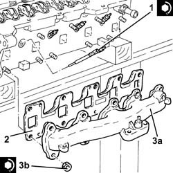
UPPER CYLINDER HEAD
Position the camshaft housing in the vice using the tool.
| Name | Country | |
|---|---|---|
| Mount | 1.860.470.001 |
Place the camshafts back in their housings.
Place the camshaft gears back in their housings and secure them without tightening the bolts.
1. Fit the camshaft timing tools.
Fit the tool positioning it with the millings in a horizontal position and checking that it is correctly inserted in the housings in the camshafts.
| Name | Country | |
|---|---|---|
| 1 | Gauge | 1.870.896.900 |
2. Tighten the camshaft sprocket fixing bolts to the recommended torque.
| Fastening | Component | Ø | Value (daNm) | |
|---|---|---|---|---|
| 2 | Bolt | CYLINDER HEAD EXTENSION | M12 | (Camshaft side) 10.8 ÷ 13.2 |
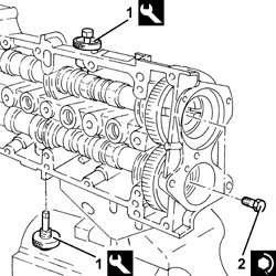
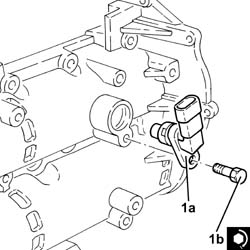
1. Place the cam angle sensor (1a) back in its housing and secure it tightening the bolt (1b) to the recommended torque.
| Fastening | Component | Ø | Value (daNm) | |
|---|---|---|---|---|
| 1b | Bolt | CAM ANGLE SENSOR | M6 | (Camshaft housing side) 0.6 ÷ 0.8 |
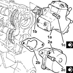
1. Place the pressure pump (1a), complete with coupling (1b) and new O-ring, back in its housing and fix it tightening the bolts (1c) to the recommended torque.
| Fastening | Component | Ø | Value (daNm) | |
|---|---|---|---|---|
| 1c | Bolt | PRESSURE PUMP | M7 | (Camshaft housing side) 1.4 ÷ 1.7 |
2. Place the vacuum unit (2a), complete with gasket (2b), back in its housing and secure it tightening the bolts (1c) to the recommended torque.
Follow the order shown in the diagram for each tightening sequence. Tighten to 2.0 daNm in two stages: an initial stage of 0.5 daNm following tightening to 1.8 - 2.2 daNm.
| Fastening | Component | Ø | Value (daNm) | |
|---|---|---|---|---|
| 2c | Bolt | BRAKE SERVO VACUUM PUMP | M8 | (Cylinder head side) 1.8 ÷ 2.2 |
Remove the support tool, complete with upper cylinder head from the vice and separate them.
Parts & tools for this job Staging For 2003 Fiat Panda
- PARTEngine gasket setSearch: Fiat Panda 2003 engine gasket set
- TOOLTorque wrenchSearch: 3/8 inch torque wrench
- TOOLFeeler gauge setSearch: feeler gauge set
Links open Amazon search results in a new tab. As an Amazon Associate I earn from qualifying purchases.