
Horns
- Make
- Fiat
- Model
- Panda Factory Service Manual
- Year
- 2003–2012
- Section
- Manoeuvring and warning signals › Horns
Horns
The diagram below shows a view of the assembly.
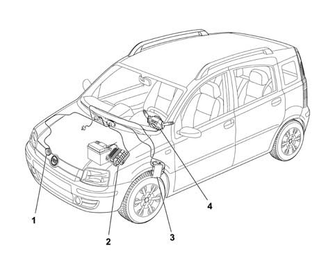
1 - Horn
2 - Engine wiring box
3 - Facia Node
4 - Stalk unit
The electromagnetic horn is secured to a steel bracket and positioned in the central upper part of the vehicle behind the front grille.
The activation signal is given by pressing the centre section of the steering wheel by the spokes.
View of horn assembly

1 - Bracket
2 - Horn
3 - Connector
The specifications of the electromagnetic horn are as follows:
- rated voltage: 13V
- current uptake: <= 6 A
- sound level: 110 - 118 dB/A
- frequency: 420 ± 40 Hz.
When pressure is exercised on the covering in the middle of the steering wheel, one of the three springs in the rear of the air bag module is pressed and the circuit is closed to earth.
View of horn control circuit
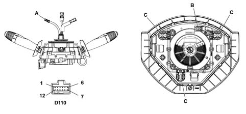
A - Horn connection on clockspring
B - Horn connection on airbag module
C - Spring
D110 - Connection on clockspring
D110 - pin 7: Horn earth
D110 - pin 8: Horn
The three springs form part of a printed circuit, located on the lower airbag module partition which ends with a two-way connection.
The connection to the system, via the clock spring, allows the rotation of the steering wheel, ensuring the correct transmission of the various signals, without the aid of sliding contacts.
Parts & tools for this job Staging For 2003 Fiat Panda
- PARTReplacement bulbsSearch: Fiat Panda 2003 bulbs
- TOOLDigital multimeterSearch: automotive digital multimeter
Links open Amazon search results in a new tab. As an Amazon Associate I earn from qualifying purchases.