
Piston, pin set - replace
- Make
- Alfa Romeo
- Model
- GT Factory Service Manual
- Year
- 2003–2010
- Section
- Pistons and connecting rods › Piston, pin set - replace
PISTON, PIN SET - REPLACE
Removing
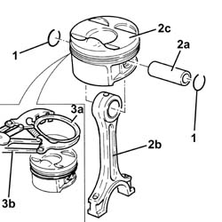
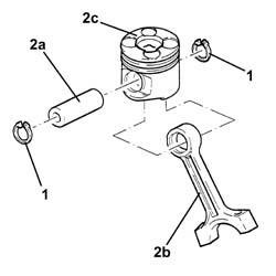
1. Remove the circlips.
2. Remove the pins (2a) and separate the connecting rods (2b) from the pistons (2c).
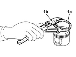
3. Remove the piston rings (3a) from the pistons using a suitable tool (3b).
Refitting
Check the alignment of the connecting rods using a suitable tool; if the connecting rod is not perfectly aligned, replace it.
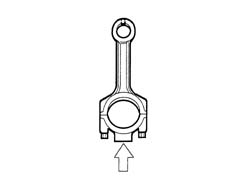
Check that the difference in weight between the connecting rods, complete with bearing shells, caps and bolts, is within the recommended values.
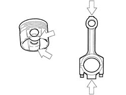
The arrows in the diagram show the areas where material can be removed from in order to equalize the weight.
| Measurement | Value | ||
|---|---|---|---|
| Maximum difference in weight between connecting rods (g.) | ± 5 |
Check that the difference in weight between the pistons is within the recommended values.
| Measurement | Value | ||
|---|---|---|---|
| Maximum difference in weight between pistons (g.) | ± 5 |
If the weight difference between pistons is not as specified, replace the worn parts.
Fit the piston rings on the pistons using a suitable tool.
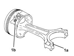
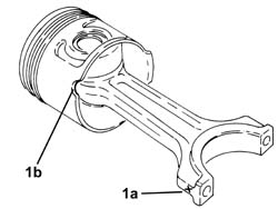
1. Join the connecting rods to the pistons so that safety notch (1a) on the big end of the connecting rod for the relevant half-bearing is on the side indicated by the arrow (1b) stamped on the piston skirt.
Refit the pins and secure using piston rings.
Removing
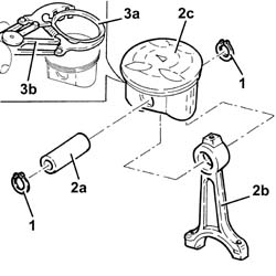
1. Remove the circlips.
2. Remove the pins (2a) and separate the connecting rods (2b) from the pistons (2c).
3. Remove the piston rings (3a) from the pistons using a suitable tool (3b).
Refitting
Check the alignment of the connecting rods using a suitable tool; if the connecting rod is not perfectly aligned, replace it.
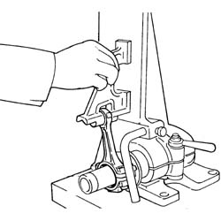
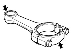
Check that the difference in weight between the connecting rods, complete with bearing shells, caps and bolts, is within the recommended values.
The arrows in the diagram show the areas from where material can be removed in order to equalize the weight.
| Measurement | Value | ||
|---|---|---|---|
| Maximum difference in weight between connecting rods (g.) | ± 5 |
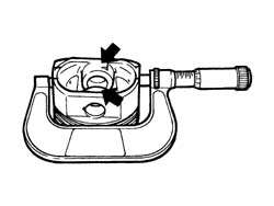
Check that the difference in weight between the pistons is within the recommended values.
The arrows in the diagram show the areas from where material can be removed in order to equalize the weight.
| Measurement | Value | ||
|---|---|---|---|
| Maximum difference in weight between pistons (g.) | ± 5 |
Refit the piston rings using a suitable tool
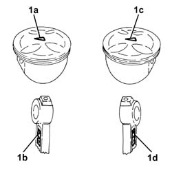
1. Join the connecting rod to the piston so that:
for the left bank, arrow (1a) stamped on the piston is turned toward the same side as the stamp (1b) on the connecting rod;
for the right bank, arrow (1c) stamped on the piston is turned towards the opposite side to the stamp on the connecting rod.
Refit the pin and secure using piston rings.
Removing
1. Remove the circlips.
2. Remove the pin (2a) and separate the connecting rod (2b) from the pistons (2c).
1. Remove the piston rings (1a) from the pistons using a suitable tool (1b).
Refitting
Check the alignment of the connecting rods using a suitable tool; if the connecting rod is not perfectly aligned, replace it.
Check that the difference in weight between the pistons is within the recommended values.
The arrows in the diagram show the areas from where material can be removed in order to equalize the weight.
| Measurement | Value | ||
|---|---|---|---|
| Piston weight difference (g.) | +- 5 |
Check that the difference in weight between the connecting rods, complete with bearing shells, caps and bolts, is within the recommended values.
The arrows in the diagram show the areas from where material can be removed in order to equalize the weight.
| Measurement | Value | ||
|---|---|---|---|
| Connecting rod weight difference (g.) | ± 2.5 |
Fit the piston rings on the pistons using a suitable tool.
1. Join the connecting rods to the pistons so that the number stamped on the big end (1a) is facing the reference (1b) on the piston skirt where the oil jet is housed.
Fit the pins and secure them using the circlips.
1. Remove the circlips
2. Remove the pins (2a) and separate the connecting rods (2b) from the pistons (2c).
3. Remove the piston rings (3a) from the pistons using a suitable tool (3b).
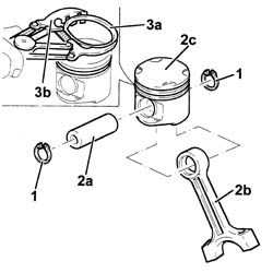
Check the alignment of the connecting rods using a suitable tool; if the connecting rod is not perfectly aligned, replace it.
Check that the difference in weight between the connecting rods, complete with half-bearings, caps and bolts, is within the recommended values.
The arrows in the diagram show the areas where material can be removed from in order to equalize the weight.
| Measurement | Value | ||
|---|---|---|---|
| Maximum difference in weight between connecting rods (g.) | ± 5 |
Check that the difference in weight between the pistons is within the recommended values.
The arrows in the diagram show the areas where material can be removed from in order to equalize the weight.
| Measurement | Value | ||
|---|---|---|---|
| Maximum difference in weight between pistons (g.) | ± 5 |
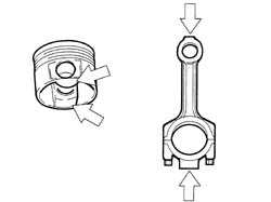
Fit the piston rings on the pistons using a suitable tool.
Assemble the connecting rods with the corresponding pistons so that the number stamped on the small end faces the large notches (for inlet valves) on the piston crown.
Fit the pin and secure it with its circlips.
Parts & tools for this job Staging For 2003 Alfa Romeo GT
- PARTEngine gasket setSearch: Alfa Romeo GT 2003 engine gasket set
- TOOLTorque wrenchSearch: 3/8 inch torque wrench
- TOOLFeeler gauge setSearch: feeler gauge set
Links open Amazon search results in a new tab. As an Amazon Associate I earn from qualifying purchases.