
Piston/cylinder liner set - r r
- Make
- Alfa Romeo
- Model
- GT Factory Service Manual
- Year
- 2003–2010
- Section
- Pistons and connecting rods › Piston/cylinder liner set - r r
PISTON/CYLINDER LINER SET - R R
Removing
Rotate the engine throughi 180° on the overhauling stand.
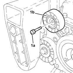
1. Undo the bolt (1a) and remove the fixed single drive belt tensioner (1b).
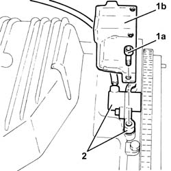
1. Undo the bolts (1a) and remove the rpm sensor protection (1b).
2. Remove the rpm sensor complete with support.
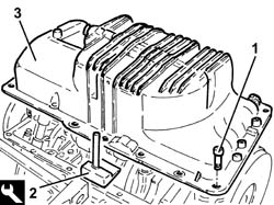
1. Undo the bolts fixing the engine oil sump.
2. Use the tool to cut the crankcase sump sealant.
| Name | Country | |
|---|---|---|
| 2 | Blade | 1.870.718.000 |
3. Remove the crankcase sump.
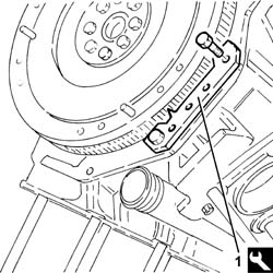
1. Fit the flywheel lock.
| Name | Country | |
|---|---|---|
| 1 | Counter-torque | 1.860.779.000 |
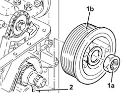
1. Undo the nut (1a) and remove the crankshaft pulley (1b).
2. Remove the timing drive belt.
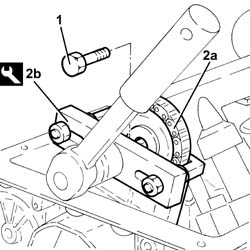
1. Unscrew the bolt securing the engine oil pump drive chain to the oil pump.
2. Move the engine oil pump drive chain (2a) away from the pump using tool (2b).
| Name | Country | |
|---|---|---|
| 2b | Extractor | 1.860.954.001 |
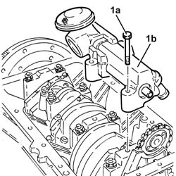
1. Undo the bolts (1a) and remove the engine oil pump (1b).
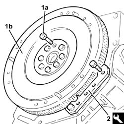
1. Undo the bolts (1a) and remove the engine flywheel (1b).
The engine flywheel retaining bolts are treated with a compound to prevent them coming undone they should therefore be replaced whenever they are removed.
2. Remove the flywheel lock.
| Name | Country | |
|---|---|---|
| 2 | Counter-torque | 1.860.779.000 |
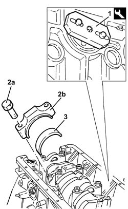
1. Fit the tool for rotating the crankshaft.
| Name | Country | |
|---|---|---|
| 1 | Flange | 1.820.618.000 |
Turn the crankshaft to gain access to the big end bearing cap bolts on the right bank.
2. Undo the bolts (2a) and remove the right big end bearing caps (2b).
3. Remove the big end bearing shells.
Rotate the engine throughi 180° on the overhauling stand.
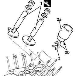
1. Remove the liner retaining tools from the right bank.
| Name | Country | |
|---|---|---|
| 1 | Liner/bore holder | 1.820.279.000 |
2. Remove the right bank cylinder liner (2a), piston and connecting rod (2b) assemblies.
Separate the piston/connecting rod assemblies from their cylinder liners.
3. Remove the big end bearing shells.
Do the same to remove the cylinder liners and connecting rod-piston assemblies for the left bank.
Refitting
Refit new seals in their seats on the cylinder liners.
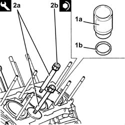
1. Place the cylinder liners complete with seals (1b) back in their housings.
2. Fit the cylinder liner retaining tools (2a) and tighten the nuts (2b) to the specified torque.
| Name | Country | |
|---|---|---|
| 2a | Liner/bore holder | 1.820.279.000 |
| Fastening | Component | Ø | Value (daNm) | |
|---|---|---|---|---|
| 2b | Nut | LINER/BORE LOCK TOOLS | M12 | 2.4 ÷ 2.6 + 228? ÷ 232? |
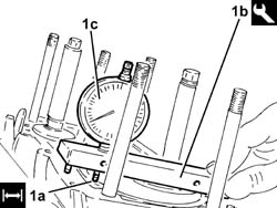
1. Measure the projection of the cylinder liners in relation to the crankcase (1a) plane using the tool (1b) fitted with a dial gauge (1c) and check that it is within the recommended limits.
| Measurement | Value | ||
|---|---|---|---|
| 1a | Cylinder bore/liner projection from crankcase plane (mm) | 0.01 ÷ 0.06 |
| Name | Country | |
|---|---|---|
| 1b | Dial gauge mounting | 1.825.003.000 |
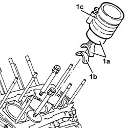
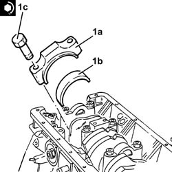
1. Refit the piston-connecting rod assemblies (1a) in their seats in the cylinder liners complete with bearing halves (1b) using a suitable tool (1c).
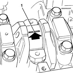
Fit the piston-connecting rod assemblies so that the arrows stamped on the piston crowns face the camshaft end.
Rotate the engine through 180° on the overhauling stand.
Turn the crankshaft to gain access to the crankpins.
1. Fit the calibrated wire (Plastigage) to measure the big end bearing clearance.
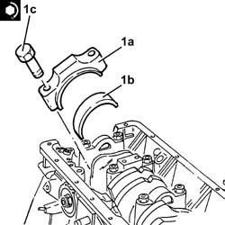
1. Refit the connecting rod cap (1a) complete with half-bearing (1b) and fix it tightening the bolts (1c) to the recommended torque.
The safety notches on the connecting rod cap and connecting rod head must be on the same side.
| Fastening | Component | Ø | Value (daNm) | |
|---|---|---|---|---|
| 1c | Bolt | Connecting rod cap | M9 | 1.9 ÷ 2.1 + 48? ÷ 52? |
Use the tool for angular tightening of the connecting rod cap bolts.
| Name | Country | |
|---|---|---|
| Protractor | 1.860.942.000 |
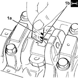
1. Remove the big end bearing caps fitted previously and, using a suitable graduated measuring instrument (1a), measure the clearance shown by the calibrated wire (1b).
Measure the clearance at all the bearings, taking care to do it one bearing at a time without ever moving the crankshaft.
| Measurement | Value | ||
|---|---|---|---|
| 1b | Main journals/bearing clearance (mm) | Category B | 0.023 ÷ 0.063 |
| Category A | 0.020 ÷ 0.060 | ||
Turn the crankshaft to gain access to the crankpins.
1. Refit the connecting rod caps (1a), complete with half-bearings (1b), and fix them tightening the bolts (1c) to the recommended torque.
The safety notches on the connecting rod cap and connecting rod head must be on the same side.
| Fastening | Component | Ø | Value (daNm) | |
|---|---|---|---|---|
| 1c | Bolt | Connecting rod cap | M9 | 1.9 ÷ 2.1 + 48? ÷ 52? |
Use the tool for angular tightening of the main bearing cap bolts.
| Name | Country | |
|---|---|---|
| Protractor | 1.860.942.000 |
Remove the tool for rotating the crankshaft.
| Name | Country | |
|---|---|---|
| Flange | 1.820.618.000 |
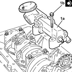
1. Place the power assisted steering pump (1a) back in its housing and fix it tightening the bolts (1b) to the recommended torque.
| Fastening | Component | Ø | Value (daNm) | |
|---|---|---|---|---|
| 1b | Bolt | ENGINE OIL PUMP | M10 | (Main journal cap side) 4.5 ÷ 5.5 |
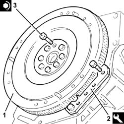
1. Refit the engine flywheel in its housing and secure by tightening the bolts to the recommended torque.
The engine flyhwheel may only be refitted in one position because the retaining bolt holes are not equidistant.
2. Fit the flywheel lock.
| Name | Country | |
|---|---|---|
| 2 | Counter-torque | 1.860.779.000 |
3. Tighten the engine flywheel retaining bolts to the specified torque.
The engine flywheel retaining bolts are treated with a compound to prevent them coming undone they should therefore be replaced whenever they are removed.
| Fastening | Component | Ø | Value (daNm) | |
|---|---|---|---|---|
| 3 | Bolt | FLYWHEEL | M12 | (Crankshaft side) 2.9 ÷ 3.2 + 48? ÷ 51? |
Use the tool for angular tightening of the engine flywheelbolts.
| Name | Country | |
|---|---|---|
| Protractor | 1.860.942.000 |
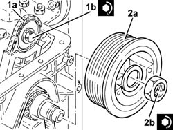
1. Refit the engine oil pump drive chain (1a) in position on the oil pump, then tighten bolt (1b) to the specified torque.
| Fastening | Component | Ø | Value (daNm) | |
|---|---|---|---|---|
| 1b | Bolt | ENGINE OIL PUMP DRIVE CHAIN | M10 | (Engine oil pump side) 4.5 ÷ 5.5 |
Position the toothed timing belt provisionally on the toothed drive pulley.
2. Place the crankshaft pulley (2a) back in its housing and secure it tightening the nut (2b) to the recommended torque.
| Fastening | Component | Ø | Value (daNm) | |
|---|---|---|---|---|
| 2b | Left thread nut | CRANKSHAFT PULLEY | M28 | (Crankshaft side) 22.8 ÷ 25.2 |
Remove the flywheel lock.
| Name | Country | |
|---|---|---|
| Counter-torque | 1.860.779.000 |
Apply the recommended sealant to the entire perimeter of the crankcase sump.
| Type | Component | Name | Qty. | |
|---|---|---|---|---|
| Sealant | OIL SUMP | LOCTITE 5900 |
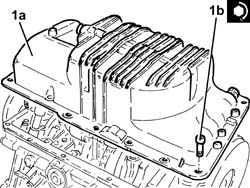
1. Place the crankcase sump (1a) back in its housing and fix it tightening the bolts (1b) to the recommended torque.
| Fastening | Component | Ø | Value (daNm) | |
|---|---|---|---|---|
| 1b | Bolt | OIL SUMP | M7 | (Engine crankcase side) 1.4 ÷ 1.7 |
Refit the rpm sensor and mount.
Replace the rear wheel rpm sensor in its housing and fix it using the bolts.
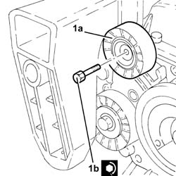
1. Place the engine components single drive belt fixed tensioner (1a) back in its housing and fix it tightening the bolt (1b) to the recommended torque.
| Fastening | Component | Ø | Value (daNm) | |
|---|---|---|---|---|
| 1b | Bolt | FIXED SINGLE SERVICE BELT TENSIONER | M8 | (Crankcase sump side) 2.3 ÷ 2.8 |
Parts & tools for this job Staging For 2003 Alfa Romeo GT
- PARTEngine gasket setSearch: Alfa Romeo GT 2003 engine gasket set
- TOOLTorque wrenchSearch: 3/8 inch torque wrench
- TOOLFeeler gauge setSearch: feeler gauge set
Links open Amazon search results in a new tab. As an Amazon Associate I earn from qualifying purchases.