
Injector cable loom - r.r.
- Make
- Alfa Romeo
- Model
- GT Factory Service Manual
- Year
- 2003–2010
- Section
- Petrol injection system › Injector cable loom - r.r.
INJECTOR CABLE LOOM - R.R.
Removing
Position the vehicle on the ramp
Proceed with removal - 1016A40 ignition coil cover on cylinder head- r+r
Proceed with removal - 1048A59 PIPE from flow meter to throttle casing hose - R.R.
Proceed with removal - 5530B10 battery - r+r
Proceed with removal - 7055B54 under-engine guard - r r
Proceed with removal - 1076B18 rigid section of exhaust pipe between catalytic converter and silencer - r + r
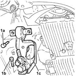
1. Undo bolts (1a) (1b) and remove the modular inlet manifold mounting bracket (1c) after releasing the wiring from the bands on the bracket.
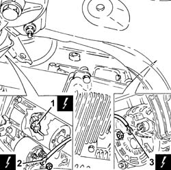
1. Disconnect the electrical connection for the rpm sensor.
| Name | Connector | |
|---|---|---|
| 1 | Rpm sensor | K46 |
2. Disconnect the earth lead from the starter motor.
| Name | Connector | |
|---|---|---|
| 2 | Starter motor | A20 |
3. Disconnect the earth lead from the alternator.
| Name | Connector | |
|---|---|---|
| 3 | Alternator | A10 |
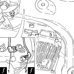
1. Disconnect the electrical connection for the knock sensor.
| Name | Connector | |
|---|---|---|
| 1 | Detonation sensor 1 | K50 |
2. Disconnect the electrical connection for the insufficient engine oil pressure sensor.
| Name | Connector | |
|---|---|---|
| 2 | Engine oil pressure sensor | K30 |
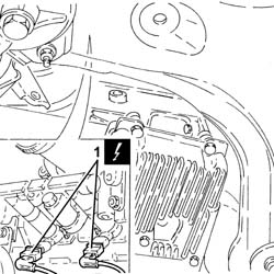
1. Disconnect the electrical connections from the injectors.
| Name | Connector | |
|---|---|---|
| 1 | Injector | N70 |
1. Disconnect the electrical connection from the fuel vapour solenoid valve.
| Name | Connector | |
|---|---|---|
| 1 | Fuel vapour recovery solenoid | L10 |
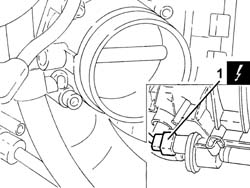
1. Disconnect the electrical connector of the fuel injector wiring loom and release it from the mounting bracket.
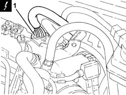
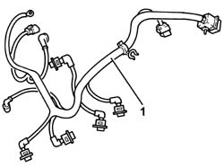
1. Release the injector wiring loom from its attachments and remove it.
Refitting
Refit the injector wiring loom in its seating and secure it with its bands.
Connect the electrical connector for the injector wiring loom and secure it to the mounting bracket.
Connect the electrical connection to the fuel vapour solenoid valve.
Connect the electrical connections to the injectors.
Connect the electrical connection to the engine oil pressure warning sensor.
Connect the electrical connection for the knock sensor.
Connect the earth lead to the alternator.
Connect the earth lead to the starter motor.
Connect the electrical connection for the rpm sensor.
Place the modular intake manifold mounting bracket back in its housing and secure it using the bolts. Then secure the electrical wiring to the bands.
Proceed with refitting - 1076B18 rigid section of exhaust pipe between catalytic converter and silencer - r + r.
Proceed with refitting - 7055B54 under-engine guard - r r.
Proceed with refitting - 5530B10 battery - r+r.
Proceed with refitting - 1048A59 PIPE from flow meter to throttle casing hose - R.R..
Proceed with refitting - 1016A40 ignition coil cover on cylinder head- r+r.
Remove the car from the ramps.
Parts & tools for this job Staging For 2003 Alfa Romeo GT
- PARTFuel filterSearch: Alfa Romeo GT 2003 fuel filter
- TOOLFuel pressure test kitSearch: fuel pressure test kit
- TOOLFuel line disconnect toolSearch: fuel line disconnect tool
Links open Amazon search results in a new tab. As an Amazon Associate I earn from qualifying purchases.