
Single cylinder head, removed - overhaul
- Make
- Alfa Romeo
- Model
- GT Factory Service Manual
- Year
- 2003–2010
- Section
- Cylinder head/s › Single cylinder head, removed - overhaul
SINGLE CYLINDER HEAD, REMOVED - OVERHAUL
Removing
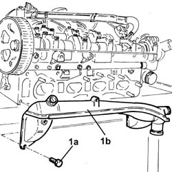
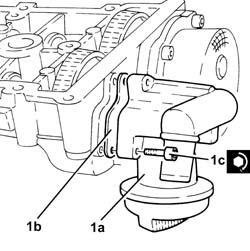
1. Undo the bolts (1a) and remove the water pump inlet pipe (1b) complete with gasket.
1. Fit the tool on the cylinder head.
| Description | Code | |
|---|---|---|
| 1 | Support | 1.860.470.001 |
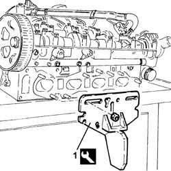
Position the cylinder head in the vice using the support tool fitted previously.
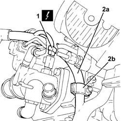
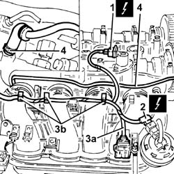
1. Disconnect the electrical connection from the engine coolant temperature sensor.
| Description | Connector | |
|---|---|---|
| 1 | Engine temperature sending unit | See K36 ENGINE TEMPERATURE SENDER UNIT ( CONNECTORS ) |
2. Release electrical wiring (2a) from band (2b).
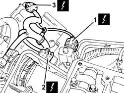
1. Disconnect the electrical connection from the fuel pressure regulator.
| Description | Connector | |
|---|---|---|
| 1 | Fuel pressure regulator | See N77 FUEL PRESSURE REGULATOR ( CONNECTORS ) |
2. Disconnect the electrical connection from the fuel pressure sensor.
| Description | Connector | |
|---|---|---|
| 2 | Fuel pressure sensor | See K83 FUEL PRESSURE SENSOR |
3. Disconnect the electrical connection from the throttle casing with D.V.L.
| Description | Connector | |
|---|---|---|
| 3 | Throttle body actuator | See N75 THROTTLE BODY ACTUATOR ( CONNECTORS ) |
1. Disconnect the electrical connection from the phase transformer solenoid.
| Description | Connector | |
|---|---|---|
| 1 | Variable valve timing actuator | See N76 TIMING VARIATOR ACTUATOR |
2. Disconnect the electrical connection from the switching control actuator enablement solenoid valve.
| Description | Connector | |
|---|---|---|
| 2 | Variable geometry solenoid valve | See L15 VARIABLE GEOMETRY CONTROL SOLENOID ( CONNECTORS ) |
3. Remove the electrical wiring (3a) after having released it from the fastenings (3b) on the modular intake manifold.
4. Loosen the band and disconnect the coolant return pipe from the engine coolant reservoir from the thermostat.
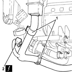
1. Release the electrical wiring from the retaining bands.
2. Disconnect the electrical connection from the fuel vapour recovery solenoid valve.
| Description | Connector | |
|---|---|---|
| 2 | Fuel vapour recovery solenoid valve | See L10 FUEL VAPOUR RECOVERY SOLENOID |
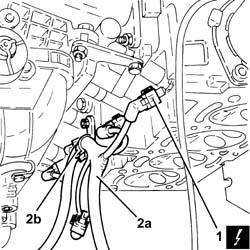
1. Disconnect the electrical connections from the injectors.
| Description | Connector | |
|---|---|---|
| 1 | Injector | See N70 INJECTOR |
2. Remove the electrical wiring (2a) after having released it from the securing band (2b).
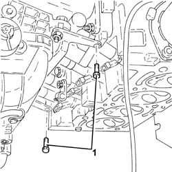
1. Undo the bolts fixing the modular intake manifold brackets.
1. Loosen the bands (1a) and remove the modular intake manifold assembly (1b).
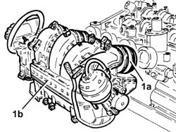
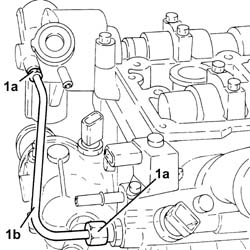
1. Undo the connectors (1a) and remove the high pressure fuel pipe (1b).
The high pressure fuel pipe should be replaced each time it is refitted.
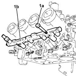
1. Undo the bolts (1a) and remove the fuel manifold pipe assembly (1b).
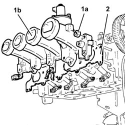
1. Undo the nuts (1a) and remove the intake manifold (1b).
2. Remove the gasket.
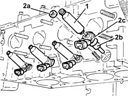
1. Remove the connectors complete with O rings from the injectors.
2. Undo the nuts (2a) and remove the injectors (2b) complete with brackets (2c).
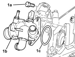
1. Undo the bolts (1a) and remove the thermostat (1b) complete with O-ring (1c).
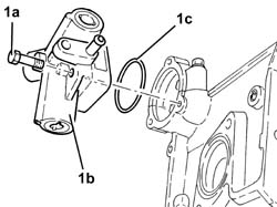
1. Undo the bolts (1a) and remove the high pressure fuel (1b) complete with O-ring (1c).
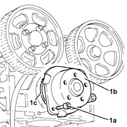
1. Undo the bolts (1a) and remove the water pump (1b) complete with O-ring (1c).
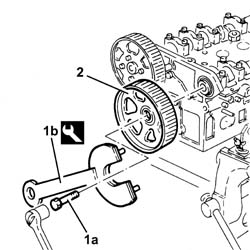
1. Undo the exhaust side driven timing pulley bolt (1a) using the tool (1b) for counter-torque.
| Description | Code | |
|---|---|---|
| 1b | Spanner for rotating timing pullies | 1.860.831.002 |
2. Remove the exhaust side timing driven pulley.
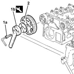
1. Undo the inlet side driven timing pulley bolt (1a) using the tool (1b) for counter-torque.
| Description | Code | |
|---|---|---|
| 1b | Counter-torque | 1.860.856.001 |
2. Remove the inlet side timing driven pulley.
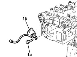
1. Undo the bolts (1a) and remove the cam angle sensor (1b).
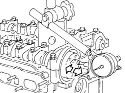
Check that the camshaft endfloat corresponds to the recommended values using a dial gauge on a magnetic base.
| Measurement | Value | ||
|---|---|---|---|
| Camshaft end float (mm) | 0.10 ÷ 0.23 |
If the endfloat for the camshafts does not correspond to the recommended values, replace the worn components when reassembling the cylinder head.
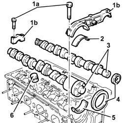
1. Undo the bolts (1a) and remove the camshaft caps (1b).
The front cap has silicon sealant therefore a plastic hammer should be used for the removal.
2. Remove the inlet side camshaft front supper upper half-bearing.
3. Remove the camshafts.
4. Remove the camshaft front oil seals.
5. Remove the inlet side camshaft front support lower half-bearing.
6. Remove the hydraulic tappets.
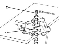
1. Position the exhaust side camshaft in a vice fitted with protective jaws.
2. Undo the pressure pump drive element and remove it.
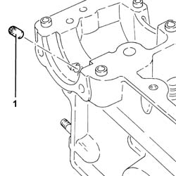
1. Remove the calibrated jet for the lubrication of the high pressure fuel pump coupling.
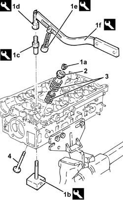
1. Remove the cotters (1a) using the tools (1b), (1c), (1d), (1e) and (1f).
| Description | Code | |
|---|---|---|
| 1b | Valve support | 1.820.011.000 |
| Description | Code | |
|---|---|---|
| 1c | Special nut | 1.820.049.000 |
| Description | Code | |
|---|---|---|
| 1d | Support | 1.821.124.000 |
| Description | Code | |
|---|---|---|
| 1e | Chamber | 1.821.205.000 |
| Description | Code | |
|---|---|---|
| 1f | Lever | 1.821.058.000 |
2. Remove the valve upper shim.
3. Remove the valve springs.
Remove the tools for dismantling the valves.
4. Remove the valve.
Carry out the same operations for removing the remaining valves.
1. Remove the valve guide oil seals (1a) using the tool (1b).
| Description | Code | |
|---|---|---|
| 1b | Extractor | 1.860.989.000 |
2. Fit the lower valve shims.
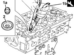
Refitting
Clean any residues of sealant from the matching surfaces of the cylinder head and the front bearing cap.
Check that the flatness of the lower cylinder head plane corresponds to the recommended values.
| Measurement | Value | ||
|---|---|---|---|
| Cylinder head lower surface flatness (mm) | 0.1 |
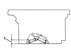
1. If the planarity of the lower cylinder head plane does not correspond to the recommended figures, regrind it without exceeding the minimum combustion chamber permitted height.
| Measurement | Value | ||
|---|---|---|---|
| 1 | Minimum combustion chamber permitted height (mm) | 12.8 ÷ 13.2 |
The volume of the combustion chamber for each cylinder is given below.
| Measurement | Value | ||
|---|---|---|---|
| Combustion chamber volume (cc) | 38.2 |
Check that the valves do not show signs of scoring or seizing.
Check that the diameter of the valve stems corresponds to the recommended figures; if not, replace the worn valves.
| Measurement | Value | ||
|---|---|---|---|
| Valve stem diameter (mm) | Inlet | 6.975 ÷ 6.990 | |
| Exhaust | 6.960 ÷ 6.975 | ||
Check that the diameter of the valve head corresponds to the recommended figures; if not, replace the valves.
| Measurement | Value | ||
|---|---|---|---|
| Valve head diameter (mm) | Inlet | 33.7 | |
| Exhaust | 28.2 | ||
The taper of the valve contact band in relation to the valve seat is indicated below.
| Measurement | Value | ||
|---|---|---|---|
| Contact band taper in relation to valve seat (-) | 45° 30'' |
Check that the outer diameter of the hydraulic tappets corresponds to the recommended figures; if not, replace the worn components.
| Measurement | Value | ||
|---|---|---|---|
| External hydraulic tappet diameter (mm) | 32.959 ÷ 32.975 |
Check that the diameter of the hydraulic tappet housings corresponds to the recommended figures; if not, replace the cylinder head.
| Measurement | Value | ||
|---|---|---|---|
| Hydraulic tappet housing diameter (mm) | 33.000 ÷ 33.025 |
Check that the length of the valve springs when released is within the recommended values.
| Measurement | Value | ||
|---|---|---|---|
| Valve spring free length (mm) | Outer | 46.0 | |
| Inner | 39.0 | ||
Using a torque wrench, check that the valve spring specifications correspond to the recommended figures; if not, replace the worn components.
| Measurement | Value | ||
|---|---|---|---|
| External valve spring height (mm) | 35.0 | ||
| Test load (daN) | 25.0 ÷ 27.4 | ||
| Measurement | Value | ||
|---|---|---|---|
| External valve spring height (mm) | 24.4 | ||
| Test load (daN) | 49.4 ÷ 53.4 | ||
| Measurement | Value | ||
|---|---|---|---|
| Internal valve spring height (mm) | 28.7 | ||
| Test load (daN) | 11.6 ÷ 12.6 | ||
| Measurement | Value | ||
|---|---|---|---|
| Internal valve spring height (mm) | 18.1 | ||
| Test load (daN) | 23.6 ÷ 25.6 | ||
Check that the diameter of the camshaft bearings corresponds to the recommended figures; if not, replace the worn camshaft.
| Measurement | Value | ||
|---|---|---|---|
| Camshaft journal diameter (mm) | 26.000 ÷ 26.015 |
Check that the nominal camshaft cam lift corresponds to the recommended figures; if not, replace the worn camshaft.
| Measurement | Value | ||
|---|---|---|---|
| Nominal camshaft cam lift (mm) | Inlet | 10.6 | |
| Exhaust | 10.2 | ||
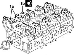
1. Place the camshaft caps (1a) in their housings in the cylinder head and tighten the bolts (1b) to the recommended torque.
| Fastening | Component | Ø | Value (daNm) | |
|---|---|---|---|---|
| 1b | Bolt | CAMSHAFT SUPPORTS | M7 | (Cylinder head side) 1.4 - 1.7 |
Check that the diameter of the camshaft supports corresponds to the recommended figures; if not, replace the cylinder head.
| Measurement | Value | ||
|---|---|---|---|
| Camshaft support diameter (mm) | 26.045 - 26.070 |
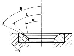
Regrind the valve seats to the recommended size, if necessary.
| Measurement | Value | ||
|---|---|---|---|
| Valve seat upper band angle "a" (-) | 150° |
| Measurement | Value | ||
|---|---|---|---|
| Angle "b" of contact band with valves (-) | 90° ± 10'' |
| Measurement | Value | ||
|---|---|---|---|
| Angle "c" of valve seat lower band (-) | 30° |
| Measurement | Value | ||
|---|---|---|---|
| Width "L" of contact band with valves (mm) | Inlet | 0.8 | |
| Exhaust | 1.0 | ||
Fit the support tool on the cylinder head.
| Description | Code | |
|---|---|---|
| Support | 1.860.470.001 |
Position the cylinder head in the vice using the support tool fitted previously.
Place the lower valve shims in their housings.
1. Temporarily position the valve (1a) in the seat and fit the tool (1b) for centering the valve guide oil seals on it.
| Description | Code | |
|---|---|---|
| 1b | Drift | 1.860.814.001 |
2. Manually fit the valve guide oil seal, then remove the centering tool.
3. Fit the valve guide oil seal using the tool.
| Description | Code | |
|---|---|---|
| 3 | Fitting tool | 1.860.812.000 |
Carry out the same operations to refit the remaining valve guide oil seals.
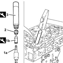
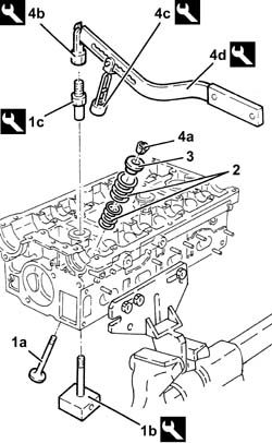
1. Fit the valve (1a) in its seat and support it using the tools (1b) and (1c).
| Description | Code | |
|---|---|---|
| 1b | Valve support | 1.820.011.000 |
| Description | Code | |
|---|---|---|
| 1c | Special nut | 1.820.049.000 |
2. Place the valve springs in their housings.
3. Refit the upper valve shim
4. Place the cotters (4a) in their housings using the tools (4b), (4c) and (4d).
| Description | Code | |
|---|---|---|
| 4b | Support | 1.821.124.000 |
| Description | Code | |
|---|---|---|
| 4c | Chamber | 1.821.205.000 |
| Description | Code | |
|---|---|---|
| 4d | Lever | 1.821.058.000 |
Carry out the same operations to refit the remaining valves.
Remove the tools for dismantling/reassembling the valves.
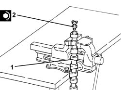
Place the calibrated jet for the lubrication of the high pressure fuel pump coupling in position.
1. Position the exhaust side camshaft in a vice fitted with protective jaws.
2. Place the the pressure pump drive element in its housing on the exhaust side camshaft and tighten it to the recommended torque.
| Fastening | Component | Ø | Value (daNm) | |
|---|---|---|---|---|
| 2 | PRESSURE PUMP DRIVE ELEMENT | M12 | (Exhaust camshaft side) 8.2 - 10.0 |
Place the hydraulic tappets in their housings.
Place the inlet side camshaft front support lower half-bearing in its housing.
Place the camshafts in their housings.
Place the inlet side camshaft front support upper half-bearing in its housing.
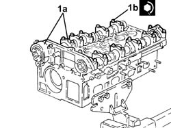
1. - Place the camshaft caps (1a) in their housings and secure them tightening the bolts (1b) to the recommended torque.
Apply silicon sealant between the front cap and the cylinder head.
| Fastening | Component | Ø | Value (daNm) | |
|---|---|---|---|---|
| 1b | Bolt | CAMSHAFT SUPPORTS | M7 | (Cylinder head side) 1.4 - 1.7 |
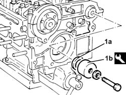
1. Fit the exhaust side camshaft front oil seal (1a) in place using the tool (1b).
| Description | Code | |
|---|---|---|
| 1b | Fitting tool | 1.821.228.000 |
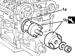
1. Fit the inlet side camshaft front oil seal (1a) in place using the tool (1b).
| Description | Code | |
|---|---|---|
| 1b | Fitting tool | 1.821.252.000 |
Fit the cam angle sensor in place and secure it using the bolts.
Refit the inlet side toothed driven pulley in its seat and secure with the bolts without tightening them.
Refit the exhaust side toothed driven pulley in its seat and secure with the bolt without tightening.
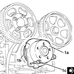
1. Position the water pump (1a), complete with O-ring (1b), in its housing and secure it tightening the bolts (1c) to the recommended torque.
| Fastening | Component | Ø | Value (daNm) | |
|---|---|---|---|---|
| 1c | Bolt | COOLANT PUMP | M8 | (Cylinder head side) 2.3 - 2.8 |
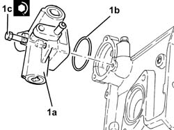
1. Position the high pressure fuel pump (1a), complete with O-ring (1b), in its housing and secure it tightening the bolts (1c) to the recommended torque.
| Fastening | Component | Ø | Value (daNm) | |
|---|---|---|---|---|
| 1c | Bolt | HIGH PRESSURE FUEL PUMP | M6 | (Cylinder head side) 0.8 - 1.0 |
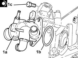
1. Place the thermostat (1a) in its housing with the O-ring (1b) and secure it by tightening the bolts (1c) to the recommended torque.
| Fastening | Component | Ø | Value (daNm) | |
|---|---|---|---|---|
| 1c | Bolt | THERMOSTAT | M8 | (Cylinder head side) 2.3 - 2.8 |
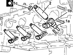
1. Place the injectors (1a) in their seats complete with brackets (1b) and fasten them tightening the nuts (1c) to the recommended torque.
| Fastening | Component | Ø | Value (daNm) | |
|---|---|---|---|---|
| 1c | Self-braking nut | INJECTORS | M6 | (Intake manifold side) 0.5 - 0.6 |
2. Place the connectors complete with O rings in their seats on the injectors.
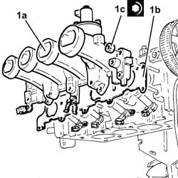
1. Refit the intake manifold (1a) complete with gasket (1b) back in its housing and secure it tightening the nuts (1c) to the recommended torque.
| Fastening | Component | Ø | Value (daNm) | |
|---|---|---|---|---|
| 1c | Nut | INLET MANIFOLD | M8 | (Cylinder head side) 2.3 - 2.8 |
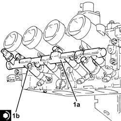
1. Place the fuel manifold (1a) in its housing and secure it tightening the bolts (1b) to the recommended torque.
| Fastening | Component | Ø | Value (daNm) | |
|---|---|---|---|---|
| 1b | Bolt | FUEL MANIFOLD | M9 | (Intake manifold side) 3.9 - 4.7 |
1. Position a new high pressure fuel pipe (1a) and secure it tightening the connectors (1b) and (1c) to the recommended torque.
| Fastening | Component | Ø | Value (daNm) | |
|---|---|---|---|---|
| 1b | Connector | HIGH PRESSURE FUEL PIPE | M10 | (High pressure pump side) 1.2 - 1.6 |
| Fastening | Component | Ø | Value (daNm) | |
|---|---|---|---|---|
| 1c | Connector | HIGH PRESSURE FUEL PIPE | M12 | (Fuel manifold pipe side) 2.0 - 2.4 |
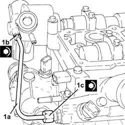
Place the modular intake manifold assembly back in its housing and tighten the bands.
Tighten the bolts fixing the modular intake manifold brackets.
Place the electrical wiring in position and fasten it with the band.
Connect the electrical connections to the injectors.
Connect the electrical connection to the fuel vapour recovery solenoid valve.
Secure the electrical wiring with the bands.
Place the coolant return pipe to the engine coolant reservoir in position, connect it to the thermostat and tighten the band.
Place the electrical wiring in position and fasten it to the modular intake manifold.
Connect the electrical connection to the switching control actuator enablement solenoid valve.
Connect the electrical connection to the phase transformer solenoid.
Connect the electrical connection to the throttle casing with D.V.L.
Connect the electrical connection to the fuel pressure sensor.
Connect the electrical connection to the fuel pressure regulator.
Secure the electrical wiring to the band.
Connect the electrical connection to the engine coolant temperature sensor.
Remove the cylinder head from the support tool.
| Description | Code | |
|---|---|---|
| Support | 1.860.470.001 |
Place the water pump rigid inlet pipe, complete with gasket, in position and secure it using the bolts.
Removing
CYLINDER HEAD EXTENSION
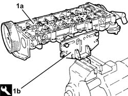
1. Position the camshaft housing (1a) in a vice using the tool (1b).
| Description | Code | |
|---|---|---|
| 1b | Support | 1.860.470.001 |
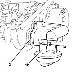
1. Undo the bolts (1a) and remove the engine oil filler (1b).
2. Remove the gasket.
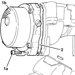
1. Undo the bolts (1a) and remove the vacuum unit (1b).
2. Remove the gasket.
1. Undo the bolt (1a) and remove the cam angle sensor (1b).
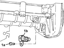
Check that the camshaft endfloat is within the recommended values using a dial gauge.
If the camshaft endfloat is not within the recommended values, replace the worn components when reassembling the cylinder head.
1. Remove plug (1a) and fit camshaft timing tools (1b) to the cylinder head extension.
Check that the tools are correctly fitted in the housings in the camshafts.
| Description | Code | |
|---|---|---|
| 1b | Templates | 1.870.896.900 |
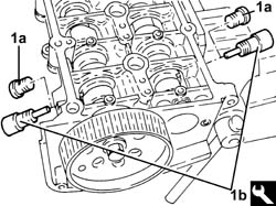
1. Undo the bolts fixing the camshaft gears.
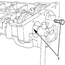
1. Undo the bolt (1a) and the exhaust side camshaft drive pulley (1b).
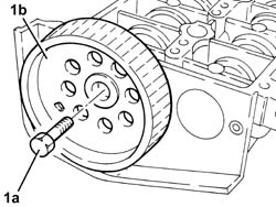
Remove the camshaft timing tools from the camshaft housing.
| Description | Code | |
|---|---|---|
| Templates | 1.870.896.900 |
1. Release the camshafts (1a), as necessary and remove the camshaft gears (1b).
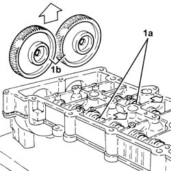
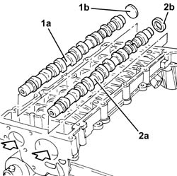
1. Using a suitable drift, extract the inlet side camshaft (1a) and plug (1b).
2. Using a suitable drift, extract the exhaust side camshaft (2a) and oil seal (2b).
Remove the exhaust side camshaft oil seal.
1. Undo and remove the engine oil lubrication duct plugs.
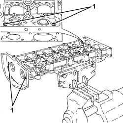
Remove the support tool complete with camshaft housing from the vice and separate them.
LOWER CYLINDER HEAD
1. Position the lower cylinder head (1a) in a vice using the tool (1b).
| Description | Code | |
|---|---|---|
| 1b | Support | 1.860.470.001 |
2. Remove the hydraulic tappets.
3. Undo the bolts (3a) and remove the thermostat (3b).
Remove the gasket.
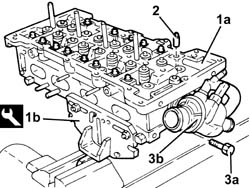
1. Undo the bolts (1a) and remove the water pump (1b).
2. Remove the gasket.
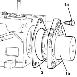
1. Fit a wooden stand on the cylinder head plane to support the valves and secure it using bolts.
| Description | Code | |
|---|---|---|
| 1 | Stand | 1.860.804.001 |
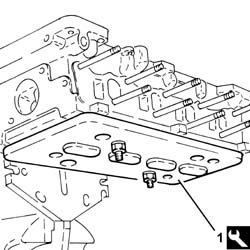
1. Fit the half-cones (1a) using the tools (1b) and (1c).
| Description | Code | |
|---|---|---|
| 1b | Lever | 1.860.644.001 |
| Description | Code | |
|---|---|---|
| 1c | Chamber | 1.870.890.000 |
2. Remove the valve upper shim.
3. Remove the valve spring.
4. Remove the shim (for exhaust valves only).
5. Remove the valve guide oil seal with integrated lower valve shim.
Carry out the same operations on the other valves.
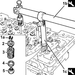
Remove the wooden stand and recover the valves.
| Description | Code | |
|---|---|---|
| Stand | 1.860.804.001 |
Remove the lower cylinder head from the support tool.
| Description | Code | |
|---|---|---|
| Support | 1.860.470.001 |
Replace the valve guide
Op. 1016E14 SINGLE CYLINDER HEAD VALVE GUIDES - REPLACE DURING OPERATION 1016E10.
Refitting
Clean any residues of the old gasket from the lower cylinder head plane.
Check that the flatness of the lower cylinder head plane corresponds to the recommended values.
| Measurement | Value | ||
|---|---|---|---|
| Lower plane planarity (mm) | 0.1 ± 0.05 |
1. If the planarity of the lower cylinder head plane does not correspond to the recommended figures, regrind it without exceeding the minimum permitted height.
| Measurement | Value | ||
|---|---|---|---|
| Minimum permitted height (mm) | 107.0 ± 0.05 |
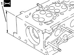
Check that the valves do not show signs of scoring or seizing.
Check that the diameter of the valve stems corresponds to the recommended figures; if not, replace the worn valves.
| Measurement | Value | ||
|---|---|---|---|
| Stem diameter (mm) | Inlet | 5.982 ÷ 6.000 | |
| Exhaust | 5.972 ÷ 5.990 | ||
Check that the length of the valve springs when released is within the recommended values.
| Measurement | Value | ||
|---|---|---|---|
| Free length (mm) | 43.1 |
Using a torque wrench, check that the valve spring specifications correspond to the recommended figures; if not, replace the worn components.
| Measurement | Value | ||
|---|---|---|---|
| Length (mm) | 34.0 | ||
| Under a load of (daN) | 20.17 ÷ 21.42 | ||
| Measurement | Value | ||
|---|---|---|---|
| Length (mm) | 24.5 | ||
| Under a load of (daN) | 42.82 ÷ 45.47 | ||
Check that the diameter of the camshaft bearings corresponds to the recommended figures; if not, replace the worn camshaft/s.
| Measurement | Value | ||
|---|---|---|---|
| Journal diameter (mm) | First journal | 43.600 ÷ 43.615 | |
| Fourth journal | 43.000 ÷ 43.015 | ||
| Fifth journal | 30.000 ÷ 30.015 | ||
| Second journal | 43.400 ÷ 43.415 | ||
| Third journal | 43.200 ÷ 43.215 | ||
Check that the nominal camshaft cam lift corresponds to the recommended figures; if not, replace the worn camshaft/s.
| Measurement | Value | ||
|---|---|---|---|
| Nominal cam height (mm) | Inlet | 8.0 | |
| Exhaust | 8.0 | ||
1. Check that the diameter of the camshaft bearings corresponds to the recommended figures; if not, replace the cylinder head.
| Measurement | Value | ||
|---|---|---|---|
| Bearing diameter (mm) | First bearing | 43.646 ÷ 43.671 | |
| Fourth bearing | 43.046 ÷ 43.071 | ||
| Fifth bearing | 30.045 ÷ 30.070 | ||
| Second bearing | 43.446 ÷ 43.471 | ||
| Third bearing | 43.246 ÷ 43.271 | ||
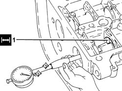
The outer diameter of the valve seats is as follows.
| Measurement | Value | ||
|---|---|---|---|
| Outer diameter (mm) | Inlet | 29.489 ÷ 29.514 | |
| Exhaust | 27.491 ÷ 27.512 | ||
1. Grind the valve seats to the recommended size.
| Measurement | Value | ||
|---|---|---|---|
| Contact band angle with inlet valve () | 45° ± 20'' |
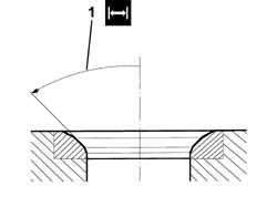
Grind the valve seats using a suitable tool.
LOWER CYLINDER HEAD
Position the lower cylinder head in the vice using the tool.
| Description | Code | |
|---|---|---|
| Support | 1.860.470.001 |
Fit the valves in the seats, then support them using the wooden stand and secure it using suitable bolts.
| Description | Code | |
|---|---|---|
| Stand | 1.860.804.001 |
1. Place the valve guide oil seal (1a) in position using the tool (1b).
| Description | Code | |
|---|---|---|
| 1b | Fitting tool | 1.870.897.100 |
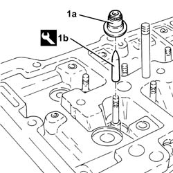
1. Place the shim in position (for exhaust valves only).
2. Fit the valve spring in its seat.
3. Refit the upper valve shim.
4. Place the cotters (4a) in their housings using the tools (4b) and (4c).
| Description | Code | |
|---|---|---|
| 4b | Lever | 1.860.644.001 |
| Description | Code | |
|---|---|---|
| 4c | Chamber | 1.870.890.000 |
Carry out the same operations on the other valves.
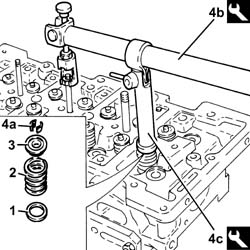
Remove the wooden stand for supporting the valves from the cylinder head plane.
| Description | Code | |
|---|---|---|
| Stand | 1.860.804.001 |
1. Position the water pump (1a), complete with gasket (1b), in its housing and secure it tightening the bolts (1c) to the recommended torque.
| Fastening | Component | Ø | Value (daNm) | |
|---|---|---|---|---|
| 1c |
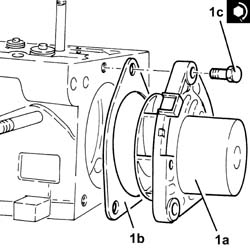
1. Place the thermostat (1a) complete with gasket back in its housing and secure it by tightening the bolts (1b) to the recommended torque.
| Fastening | Component | Ø | Value (daNm) | |
|---|---|---|---|---|
| 1b |
2. Place the hydraulic tappets in their housings.
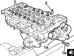
Remove the lower cylinder head from the support tool.
| Description | Code | |
|---|---|---|
| Support | 1.860.470.001 |
CYLINDER HEAD EXTENSION
1. Position the camshaft housing (1a) in a vice using the tool (1b).
| Description | Code | |
|---|---|---|
| 1b | Support | 1.860.470.001 |
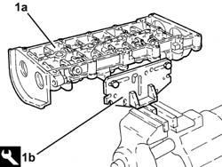
Tighten the engine oil lubrication duct plugs.
Place the camshafts in their housings.
Place the camshaft caps in their housings and secure them without tightening the bolts.
1. Fit the camshaft timing tools.
Check that the tools are correctly fitted in the housings in the camshafts.
| Description | Code | |
|---|---|---|
| 1 | Templates | 1.870.896.900 |
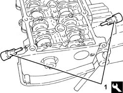
1. Tighten the camshaft gear fixing bolts to the recommended torque.
| Fastening | Component | Ø | Value (daNm) | |
|---|---|---|---|---|
| 1 |
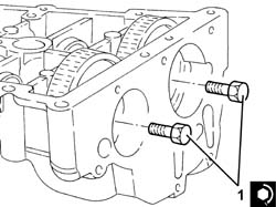
1. Fit the exhaust side camshaft front oil seal (1a) using the tool (1b).
| Description | Code | |
|---|---|---|
| 1b | Fitting tool | 1.870.896.800 |
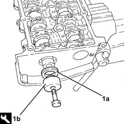
Fit the intake side camshaft plug.
Place the exhaust side camshaft toothed drive pulley in its housing and secure it without tightening the bolt.
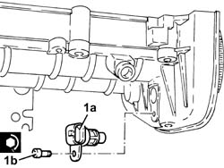
1. Position the cam angle sensor (1a) in its housing and secure it tightening the bolt (1b) to the recommended torque.
| Fastening | Component | Ø | Value (daNm) | |
|---|---|---|---|---|
| 1b |
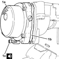
1. Place the vacuum pump (1a), complete with gasket (1b), back in its housing and secure it tightening the bolts (1c) to the recommended torque.
| Fastening | Component | Ø | Value (daNm) | |
|---|---|---|---|---|
| 1c |
1. Place the engine oil filler (1a), complete with gasket (1b), back in its housing and secure it tightening the bolts (1c) to the recommended torque.
| Fastening | Component | Ø | Value (daNm) | |
|---|---|---|---|---|
| 1c |
Remove the support tool complete with camshaft housing from the vice and separate them.
Removing
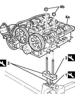
1. Place the tool in the vice.
| Description | Code | |
|---|---|---|
| 1 | Support | 1.820.012.000 |
2. Fit the tool.
| Description | Code | |
|---|---|---|
| 2 | Support | 1.820.258.000 |
3. Fit the tool.
| Description | Code | |
|---|---|---|
| 3 | Spacer | 1.820.267.000 |
4. Position the cylinder head (4a) on the support tools and fasten it using the nuts (4b).
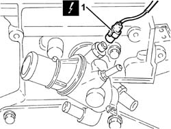
1. Disconnect the electrical connection from the engine coolant temperature sensor.
| Description | Connector | |
|---|---|---|
| 1 | Engine temperature sending unit | K36 |
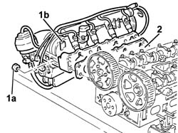
1. Undo the nuts (1a) and remove the modular intake manifold assembly (1b).
2. Remove the seal.
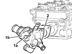
1. Undo the bolts (1a) and remove the thermostat assembly (1b).
2. Remove the seal.
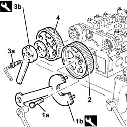
1. Undo the exhaust side driven timing pulley bolt (1a) using the tools (1b) for counter-torque.
| Description | Code | |
|---|---|---|
| 1b | Counter-torque | 1.822.146.000 |
| Description | Code | |
|---|---|---|
| 1b | Counter-torque | 1.822.156.000 |
2. Remove the exhaust side timing drive pulley.
3. Undo the inlet side camshaft drive pulley bolts (3a) using the tool (3b) for counter-torque.
| Description | Code | |
|---|---|---|
| 3b | Counter-torque | 1.822.155.000 |
4. Remove the inlet side camshaft drive pulley.
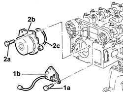
1. Undo the bolt (1a) and remove the cam angle sensor (1b).
2. Undo the bolts (2a) and remove the water pump (2b) complete with O-ring (2c).
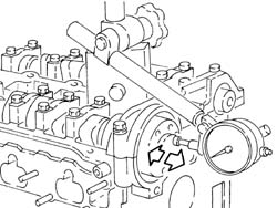
Check that the camshaft endfloat corresponds to the recommended values using a dial gauge on a magnetic base.
| Measurement | Value | ||
|---|---|---|---|
| Camshaft end float (mm) | 0.10 ÷ 0.23 |
If the endfloat for the camshafts does not correspond to the recommended values, replace the worn components when reassembling the cylinder head.
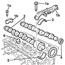
1. Undo the bolts (1a) and remove the camshaft caps (1b).
2. Remove the inlet side camshaft front supper upper half-bearing.
3. Remove the camshafts.
4. Remove the camshaft front oil seals.
5. Remove the inlet side camshaft front support lower half-bearing.
6. Remove the hydraulic tappets.
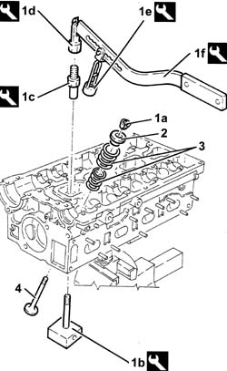
1. Remove the cotters (1a) using the tools (1b), (1c), (1d), (1e) and (1f).
| Description | Code | |
|---|---|---|
| 1b | Valve support | 1.820.011.000 |
| Description | Code | |
|---|---|---|
| 1c | Special nut | 1.820.049.000 |
| Description | Code | |
|---|---|---|
| 1d | Support | 1.821.124.000 |
| Description | Code | |
|---|---|---|
| 1e | Chamber | 1.821.205.000 |
| Description | Code | |
|---|---|---|
| 1f | Lever | 1.821.058.000 |
2. Remove the valve upper shim.
3. Remove the valve springs.
Remove the tools for dismantling the valves.
4. Remove the valve.
Carry out the same operations for removing the remaining valves.
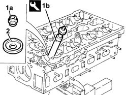
1. Remove the valve guide oil seal (1a) using the tool (1b).
| Description | Code | |
|---|---|---|
| 1b | Extractor | 1.821.208.000 |
2. Remove the lower valve shim.
Remove the cylinder head from the support tools and place it on a special workbench.
1. Thread the special extraction tool (1b) in the valve seat (1a).
Turn the cylinder head upsidedown on the workbench.
Remove the valve seat using the extraction tool.
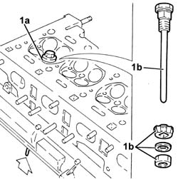
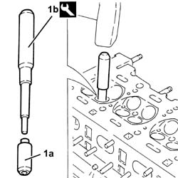
1. Remove the valve guides (1a) using the tool (1b).
| Description | Code | |
|---|---|---|
| 1b | Extractor | 1.821.176.000 |
Refitting
Clean any residues of the old gasket from the lower cylinder head plane.
Check that the flatness of the lower cylinder head plane corresponds to the recommended values.
| Measurement | Value | ||
|---|---|---|---|
| Cylinder head lower surface flatness (mm) | 0.1 |
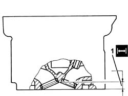
1. If the planarity of the lower cylinder head plane does not correspond to the recommended figures, regrind it without exceeding the minimum combustion chamber permitted depth.
| Measurement | Value | ||
|---|---|---|---|
| 1 | Minimum combustion chamber permitted height (mm) | 12.8 ÷ 13.2 |
Check that the valves do not show signs of scoring or seizing.
Check that the diameter of the valve stems corresponds to the recommended figures; if not, replace the worn valves.
| Measurement | Value | ||
|---|---|---|---|
| Inlet stem diameter (mm) | 6.975 ÷ 6.990 |
| Measurement | Value | ||
|---|---|---|---|
| Exhaust stem diameter (mm) | 6.960 ÷ 6.975 |
Check that the diameter of the valve head corresponds to the recommended figures; if not, replace the valves.
| Measurement | Value | ||
|---|---|---|---|
| Valve head diameter (mm) | Inlet | 33.7 | |
| Exhaust | 28.2 | ||
The taper of the valve contact band in relation to the valve seat is indicated below.
| Measurement | Value | ||
|---|---|---|---|
| Contact band taper in relation to valve seat (-) |
Check that the outer diameter of the hydraulic tappets corresponds to the recommended figures; if not, replace the worn components.
| Measurement | Value | ||
|---|---|---|---|
| External hydraulic tappet diameter (mm) | 32.959 ÷ 32.975 |
Check that the diameter of the hydraulic tappet housings corresponds to the recommended figures; if not, replace the cylinder head.
| Measurement | Value | ||
|---|---|---|---|
| Hydraulic tappet housing diameter (mm) | 33.000 ÷ 33.025 |
Check that the length of the valve springs when released is within the recommended values.
| Measurement | Value | ||
|---|---|---|---|
| Valve spring free length (mm) | Outer | 46.0 | |
| Inner | 39.0 | ||
Using a torque wrench, check that the valve spring specifications correspond to the recommended figures; if not, replace the worn components.
| Measurement | Value | ||
|---|---|---|---|
| External valve spring height (mm) | |||
| Test load (daN) | 27.1 ÷ 29.4 | ||
| Measurement | Value | ||
|---|---|---|---|
| External valve spring height (mm) | 24.5 | ||
| Test load (daN) | 48.5 ÷ 52.4 | ||
| Measurement | Value | ||
|---|---|---|---|
| Internal valve spring height (mm) | 29.5 | ||
| Test load (daN) | 9.6 ÷ 10.6 | ||
| Measurement | Value | ||
|---|---|---|---|
| Internal valve spring height (mm) | 20.0 | ||
| Test load (daN) | 20.1 ÷ 22.1 | ||
Check that the diameter of the camshaft bearings corresponds to the recommended figures; if not, replace the worn camshaft.
| Measurement | Value | ||
|---|---|---|---|
| Camshaft journal diameter (mm) | 26.000 ÷ 26.015 |
Check that the nominal camshaft cam lift corresponds to the recommended figures; if not, replace the worn camshaft.
| Measurement | Value | ||
|---|---|---|---|
| Nominal camshaft cam lift (mm) | Inlet | 9.0 | |
| Exhaust | 7.5 | ||
1. Fit the camshaft caps (1a) on the cylinder head and tighten the bolts (1b) to the recommended torque.
| Fastening | Component | Ø | Value (daNm) | |
|---|---|---|---|---|
| 1b |
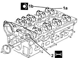
2. Check that the diameter of the camshaft supports corresponds to the recommended figures; if not, replace the cylinder head.
| Measurement | Value | ||
|---|---|---|---|
| Camshaft support diameter (mm) | 26.045 ÷ 26.070 |
Check that the outer diameter of the valve guides to be fitted corresponds to the recommended figures.
| Measurement | Value | ||
|---|---|---|---|
| Valve guide outer diameter (mm) | 13.010 ÷ 13.030 |
| Measurement | Value | ||
|---|---|---|---|
| Valve guide outer diameter oversize (mm) | 0.20 |
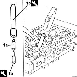
1. Fit the valve guides (1a) using the tool (1b).
| Description | Code | |
|---|---|---|
| 1b | Fitting tool | 1.821.254.000 |
Ream the valve guide inner diameter to the recommended figure.
| Measurement | Value | ||
|---|---|---|---|
| Valve guide inner diameter (mm) | 7.022 ÷ 7.040 |
Check that the outer diameter of the valve seats to be fitted corresponds to the recommended figures.
| Measurement | Value | ||
|---|---|---|---|
| Valve seat outer diameter (mm) | Inlet | 35.135 ÷ 35.150 | |
| Exhaust | 29.142 ÷ 29.157 | ||
1. Heat the cylinder head to 80° C, then fit the valve seats (1a) using a suitable tool (1b).
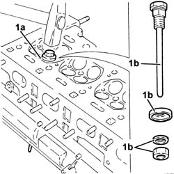
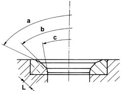
Regrind the valve seats to the recommended size.
| Measurement | Value | ||
|---|---|---|---|
| Valve seat upper band angle "a" (-) | 150° |
| Measurement | Value | ||
|---|---|---|---|
| Angle "b" of contact band with valves (-) | 90° ± 10? |
| Measurement | Value | ||
|---|---|---|---|
| Angle "c" of valve seat lower band (-) | 30° |
| Measurement | Value | ||
|---|---|---|---|
| Width "L" of contact band with valves (mm) | Inlet | 0.8 | |
| Exhaust | 1.0 | ||
Grind the valve seats using a suitable tool.
Fit the cylinder head on the support tools and fasten it using the nuts.
Fit the lower valve shim.
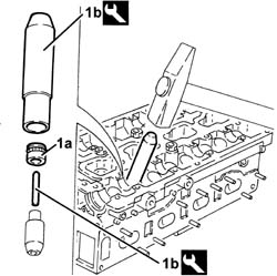
Fit the valve guide oil seal (1a) using the tool (1b).
| Description | Code | |
|---|---|---|
| 1b | Fitting tool | 1.821.206.000 |
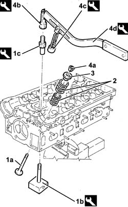
1. Fit the valve (1a) and support it using the tools (1b) and (1c).
| Description | Code | |
|---|---|---|
| 1b | Valve support | 1.820.011.000 |
| Description | Code | |
|---|---|---|
| 1c | Special nut | 1.820.049.000 |
2. Fit the valve springs.
3. Fit the valve upper shim.
4. Fit the cotters (4a) using the tools (4b), (4c), and (4d).
| Description | Code | |
|---|---|---|
| 4b | Support | 1.821.124.000 |
| Description | Code | |
|---|---|---|
| 4c | Chamber | 1.821.205.000 |
| Description | Code | |
|---|---|---|
| 4d | Lever | 1.821.058.000 |
Carry out the same operations to refit the remaining valves.
Remove the tools for dismantling/reassembling the valves.
Fit the hydraulic tappets.
Fit the inlet side camshaft front support lower half-bearing.
Fit the camshafts.
Fit the inlet side camshaft front support upper half-bearing.
1. Fit the camshaft caps (1a) and secure them tightening the bolts (1b) to the recommended torque.
| Fastening | Component | Ø | Value (daNm) | |
|---|---|---|---|---|
| 1b |
2. Fit the water pump (2a), complete with a new O-Ring (2b) and tighten the bolts (2c) to the recommended torque.
| Fastening | Component | Ø | Value (daNm) | |
|---|---|---|---|---|
| 2c |
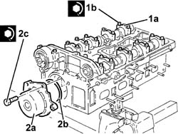
Fit the cam angle sensor and secure it using the bolt.
1. Fit the exhaust side camshaft front oil seal (1a) using the tool (1b).
| Description | Code | |
|---|---|---|
| 1b | Fitting tool | 1.821.228.000 |
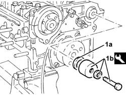
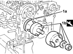
1. Fit the inlet side camshaft front oil seal (1a) using the tool (1b).
| Description | Code | |
|---|---|---|
| 1b | Fitting tool | 1.821.252.000 |
Fit the thermostat complete with gasket and fasten it tightening the fixing bolts to the recommended torque.
| Fastening | Component | Ø | Value (daNm) |
|---|
Fit the modular intake manifold, complete with gasket and secure it tightening the nuts to the recommended torque.
| Fastening | Component | Ø | Value (daNm) |
|---|
Connect the electrical connection to the engine coolant temperature sensor.
Remove the cylinder head from the support tools.
Remove the cylinder head support tools from the vice and put them down.
Parts & tools for this job Staging For 2003 Alfa Romeo GT
- PARTEngine gasket setSearch: Alfa Romeo GT 2003 engine gasket set
- TOOLTorque wrenchSearch: 3/8 inch torque wrench
- TOOLFeeler gauge setSearch: feeler gauge set
Links open Amazon search results in a new tab. As an Amazon Associate I earn from qualifying purchases.