
Ignition coil/s - r+r
- Make
- Alfa Romeo
- Model
- GT Factory Service Manual
- Year
- 2003–2010
- Section
- Engine ignition › Ignition coil/s - r+r
IGNITION COIL/S - R+R
Removing
Make sure that the ignition key is in the OFF position, then disconnect the negative battery terminal (-)
| Description | Connector | |
|---|---|---|
| Battery | See A1B BATTERY ( BATTERY NEGATIVE ) |
Proceed with the removal
Op. 1016A40 IGNITION COIL COVER ON CYLINDER HEAD- R+R.
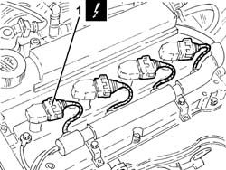
1. Disconnect the electrical connections from the ignition coils.
| Description | Connector | |
|---|---|---|
| 1 | Ignition coil | See A30 IGNITION ''COIL |
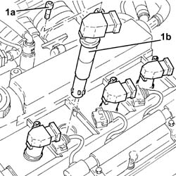
1. Undo the bolts (1a) and remove the ignition coils (1b).
Refitting
Replace the ignition coils in their housings and secure them tightening the bolts to the recommended torque.
| Fastening | Component | Ø | Value (daNm) |
|---|
Connect the electrical connections to the ignition coils.
Proceed with the refitting
Op. 1016A40 IGNITION COIL COVER ON CYLINDER HEAD- R+R.
Connect the negative battery terminal (-).
Removing
- Make sure that the ignition key is in the OFF position, then disconnect the battery terminal (-).
| Description | Connector | |
|---|---|---|
| Battery | See A001 Battery |
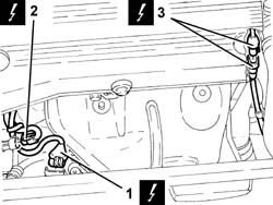
1. Disconnect the electrical connection for the right Lambda sensor.
| Description | Connector | |
|---|---|---|
| 1 | Lambda sensor | See K15 LAMBDA SENSOR ON PRE-CATALYZER |
2. Disconnect the electrical connection for the air conditioner compressor.
| Description | Connector | |
|---|---|---|
| 2 | Air conditioning compressor engagement electro-magnet | See L20 AIR CONDITIONING COMPRESSOR ENGAGEMENT SOLENOID |
3. Disconnect the electrical connection for the left Lambda sensor.
| Description | Connector | |
|---|---|---|
| 3 | Lambda sensor | See K16 LAMBDA SENSOR ON PRE-CATALYZER-2 |
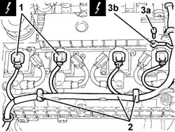
1. Disconnect the electrical connections from the ignition coils.
| Description | Connector | |
|---|---|---|
| 1 | Ignition coil | See A30 IGNITION ''COIL |
2. Release the electrical wiring from the fastenings on the tappet cover.
3. Undo the bolt (3a) and disconnect the earth lead (3b) from the ignition coil single mounting plate.
| Description | Connector | |
|---|---|---|
| 3b | Earth on engine | See C40 ENGINE EARTH |
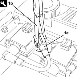
- Disconnect the high tension lead caps (1a) from the spark plugs using the tool (1b).
| Description | Code | |
|---|---|---|
| 1b | Caliper | 1.820.636.000 |
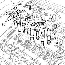
- Undo the bolts fixing the ignition coil single support plate.
- Pull the plate (2a) upwards complete with ignition coils (2b).
- At the bench, undo the bolts and separate the ignition coils from the plate.
The ignition coils are all identical and are interchangeable as long as the right cap is fitted on the large spark plug for cylinders 1 and 2 and on the small spark plug for cylinders 3 and 4.
Refitting
- Place the plate complete with ignition coils in position.
- Tighten the bolts fixing the ignition coil single support plate.
- Connect the caps for the high tension leads to the spark plugs.
- Connect the earth lead to the ignition coil single mounting plate and secure it using the bolt.
- Secure the electrical wiring using the fastenings to the tappet cover.
- Connect the electrical connections to the ignition coils.
- Connect the electrical connection for the left Lambda sensor.
- Connect the electrical connection for the air conditioner compressor.
- Connect the electrical connection for the right Lambda sensor.
- Op. 1016A40 IGNITION COIL COVER ON CYLINDER HEAD- R+R
- Connect the negative battery terminal (-).
Parts & tools for this job Staging For 2003 Alfa Romeo GT
- PARTSpark plugsSearch: Alfa Romeo GT 2003 spark plugs
- TOOLSpark plug socketSearch: spark plug socket
- TOOLSpark plug gap toolSearch: spark plug gap tool
Links open Amazon search results in a new tab. As an Amazon Associate I earn from qualifying purchases.