
Rear suspension beam - r r
- Make
- Alfa Romeo
- Model
- Brera and Spider Factory Service Manual
- Year
- 2005–2010
- Section
- Rear suspension › Rear suspension beam - r r
REAR SUSPENSION BEAM - R R
Removing
Op. 4450B13 REAR WHEELS (TWO) - R.R
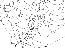
1. Unscrew the plug and drain the rear differential fluid into a special container.
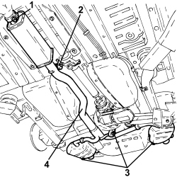
1. Loosen the collar fastening the front silencer to the catalyzer assembly.
2. Disconnect the front exhaust silencer from the flexible support mounting.
3. Disconnect the two rear silencers from the flexible mountings.
4. Remove the exhaust silencer assembly.
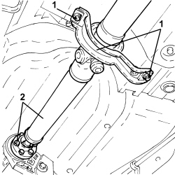
1. Unscrew the propeller shaft rear mount bolts to the body and recover any alignment spacers.
Take care to use the same alignment spacers on refitting.
2. Mark the position of the constant velocity joint with the RDA flange, unscrew the bolts securing the propeller shaft to the RDA and move aside, securing it to the body.
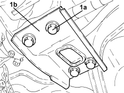
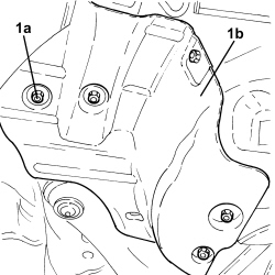
1. Unscrew bolts (1a) and remove rear suspension beam reinforcement bracket (1b).
Op. 2720C84 REAR DIFFERENTIAL TO CROSSMEMBER MOUNTING BRACKET - R.R.
1. Undo the nuts (1a) and remove rear silencer heat shield (1b), left side.
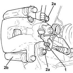
1. Disconnect the handbrake cable from the brake caliper.
2. Undo the bolts (2a) fixing the brake caliper bracket (2b) to the stub axle.
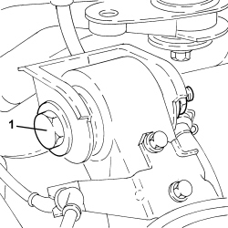
1. Undo the upper bolt fixing the stub axle to the rear suspension upper transverse arm.
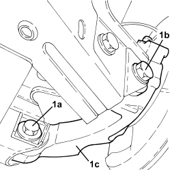
1. Loosen the bolt (1a) and undo the bolt (1b) fixing the lower stub axle (1c) to the longitudinal arm.
1. Undo the bolt (1a) securing the wheel rpm sensor (1b) to the stub axle.
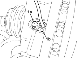
- Prise the half-axle out out of the differential.
1. Remove the steering knuckle hub complete with half-axle.
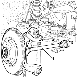
- Proceed in the same way to remove the other wheel stub axle assembly complete with half-axle.
- Position a hydraulic jack fitted with a suitable tool and support the rear differential.
1. Undo the bolts (1a) securing the rear differential (1b) to the suspension crossmember and remove it.
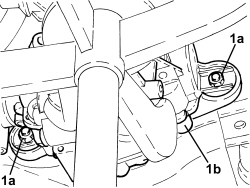
Op. 4420C10 REAR SUSPENSION STABILIZER BAR - R+R
- Position a hydraulic jack fitted with a suitable tool and support the rear suspension longitudinal arm.
1. Undo the bolt fixing the shock absorber to the rear suspension longitudinal arm.
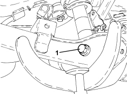
1. Unscrew the bolts and remove brackets (1a) securing the handbrake cables (1b) and move aside.
2. Undo the bolts fixing the rear suspension longitudinal arm to the bodyshell.
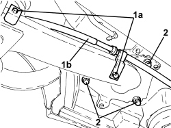
1. Unscrew bolt (1a) and remove the rear suspension longitudinal arm (1b).
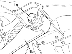
- Position a hydraulic jack fitted with a suitable tool and support the rear suspension beam.
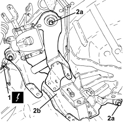
1. Disconnect the electrical connection of the headlamp alignment sensor.
2. Undo the bolts (2a) and remove the rear suspension beam (2b).
Refitting
- Assembly both longitudinal arms with the rear suspension beam without tightening the bolts to torque.
- Fit the locating tool on the lift hydraulic jack.
| Tool | Description | Function | Validity |
|---|---|---|---|
| 2000002400 | Centering tool | Rear suspension crossmember support |
| Tool | Description | Function | Validity |
|---|---|---|---|
| 1870835001 | Hydraulic lift | Rear suspension crossmember support |
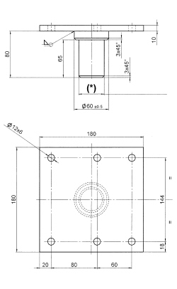
- If the above hydraulic lift is not available, use a general hydraulic lift plus the adaptor shown in the drawing, which must be made up by the workshop to allow the use of the above frames
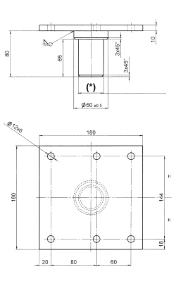
Ensure the shank diameter (*) fits the hydraulic lift used.
- Position the longitudinal arm - suspension beam assembly on the locating tool pins set up previously.
-Lift and positino the rear suspension beam assembly in its seat, taking care to locate the holes on the body using the tool reference pins.
- Tighten the bolts securing the beam to the bodyshell to torque.
| Component | Fastening | dia | Value (daNm) | Validity |
|---|---|---|---|---|
| Bodyshell side rear suspension crossmember | Bolt (to be replaced) | M12 | 11.2 ÷ 13.7 + 45° |
- Tighten the bolts securing both longitudinal arms to the bodyshell to torque.
| Component | Fastening | dia | Value (daNm) | Validity |
|---|---|---|---|---|
| Bodyshell side longitudinal arm bracket | Bolt (to be replaced) | M14 | 13.5 ÷ 16.5 + 90° |
- Remove the hydraulic lift with locating tool.
- Connect the handbrake cable to the longitudinal swinging arm using the brackets.
- Use a hydraulic jack fitted with a suitable tool to position the rear differential in its seat.
- Tighten the bolts securing the rear differential to the suspension crossmember.
| Component | Fastening | dia | Value (daNm) | Validity |
|---|---|---|---|---|
| Rear differential - suspension crossmember side | Bolt | M12 | 9.9 ÷ 12.1 | 3.2 JTS |
Op. 4420C10 REAR SUSPENSION STABILIZER BAR - R+R
- Position the wheel stub axle with half-axle in its seat andscrew in the front bolt and rear bolt securing the suspension beam without tightening to torque.
- Position the shock absorber in its seat and screw in the bolt securing it to the longitudinal swinging arm without tightening to torque.
- Position the wheel rpm sensor in its housing and secure it using the bolt.
- Connect the transverse arm to the wheel stub axle using the bolt without tightening to torque.
- Place the bracket with the brake caliper bracket back in its housing and secure it using bolts.
- Connect the handbrake cable to the brake caliper.
Op. 2720C84 REAR DIFFERENTIAL TO CROSSMEMBER MOUNTING BRACKET - R.R.
- Place the suspension beam reinforcement bracket in its housing and secure it using the bolts.
- Connect the propeller shaft to the rear differential, aligning the reference notches made between the constant velocity joint and the RDA flange on removal.
- Tighten the bolts securing the rear constant velocity joint to the RDA, interposing half-moon washers.
| Component | Fastening | dia | Value (daNm) | Validity |
|---|---|---|---|---|
| Propeller shaft - rear differential side | Bolt | M10 | 5.6 ÷ 6.8 | 3.2 JTS |
- Tighten the bolts in a cross sequence.
- Position the rear propeller shaft mount in its seat, interposing any spacers taken out on removal.
- Tighten the bolts securing the propeller shaft mount to the bodyshell to the specified torque.
| Component | Fastening | dia | Value (daNm) | Validity |
|---|---|---|---|---|
| Bodyshell side propeller shaft rear support | Bolt | M8 | 2.2 ÷ 2.6 | 3.2 JTS |
- Position the exhaust silencer assembly in its seat, connect the mounting rings, tighten the connection collar to the catalytic converter unit.
Op. 0010T54 REAR DIFFERENTIAL FLUID - REPLACE
Op. 4450B13 REAR WHEELS (TWO) - R.R
- With the vehicle positioned on a lift and in "standard 0" or "standard A" static load conditions, tighten the following fastenings, previously screwed in, to torque.
| Component | Fastening | dia | Value (daNm) | Validity |
|---|---|---|---|---|
| Steering knuckle side longitudinal arm | Bolt (to be replaced) | M14 | 9.9 ÷ 12.1 + 90° |
| Component | Fastening | dia | Value (daNm) | Validity |
|---|---|---|---|---|
| Crossmember side longitudinal arm blade | Bolt (to be replaced) | M14 | 9.5 ÷ 11.5 + 90° |
| Component | Fastening | dia | Value (daNm) | Validity |
|---|---|---|---|---|
| Longitudinal arm side shock absorber | Bolt | M14 | 13.0 ÷ 16.0 |
- Finish fitting the longitudinal swinging arm with the respective toe in and camber adjustment bolts as described in the specific "wheel geometry" procedure.
- Refer to
Op. 4450A40 REAR WHEEL GEOMETRY - CHECK USING OPTICAL EQUIPMENT, INCLUDES ADJUSTMENT IF NECESSARY
Removing
- Position the vehicle on a lift.
Op. 4450B13 REAR WHEELS (TWO) - R.R
Op. 1076B22 REAR EXHAUST SILENCERS (ONE) LH OR RH R R
Op. 1076B30 FRONT EXHAUST SILENCER - R + R
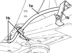
1. Release the handbrake control cables (1a) from the intermediate fastenings (1b).
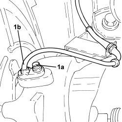
1. Unscrew bolts (1a) and remove the rear wheel rpm sensors (1b) from their stub axles and place to one side.
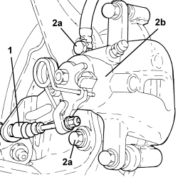
1. Disconnect the handbrake control cable from the rear brake calipers.
2. Undo the bolts (2a) and move the rear brake calipers (2b) to the side and secure them appropriately.
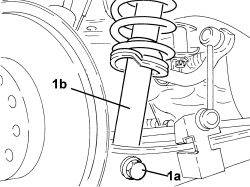
1.Unscrew bolts (1a) and disconnect the rear suspension shock absorbers (1b) from the rear suspension crossmember.
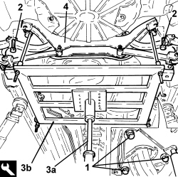
1. Loosen the bolts securing the longitudinal arms to the body.
2. Loosen the bolts fixing the rear suspension crossmember to the bodyshell.
3. Position a hydraulic jack (3a) fitted with tools (3b) to support the rear suspension crossmember.
Align the tool locating pins with the holes on the rear suspension crossmember.
| Tool | Description | Function | Validity |
|---|---|---|---|
| 2000002400 | Support | Rear suspension crossmember support |
- Fully unscrew the bolts loosened previously.
4. Lower the hydraulic jack slowly and remove the rear suspension crossmember assembly.
Refitting
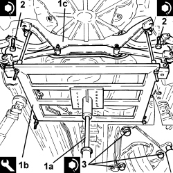
1. Place the rear suspension crossmember assembly (1c) back in its housing using the hydraulic jack (1a) and the support tool (1b).
| Tool | Description | Function | Validity |
|---|---|---|---|
| 2000002400 | Support | Rear suspension crossmember support |
- Screw in the bolts fixing the rear suspension crossmember to the bodyshell without tightening them.
- Screw in the bolts fixing the longitudinal arm to the bodyshell without tightening them.
- Remove the hydraulic jack and the tool used for supporting the rear suspension crossmember.
| Tool | Description | Function | Validity |
|---|---|---|---|
| 2000002400 | Support | Rear suspension crossmember support |
2. Tighten the new bolts fixing the rear suspension crossmember to the bodyshell to the recommended torque.
| Component | Fastening | dia | Value (daNm) | Validity |
|---|---|---|---|---|
| Rear suspension crossmember | Bolt (to be replaced) | M12 | (bodyshell side) 11.2 - 13.7 + 45° |
3. Tighten the bolts securing the longitudinal arms to the body to the specified torque.
| Component | Fastening | dia | Value (daNm) | Validity |
|---|---|---|---|---|
| Rear suspension longitudinal arm | Bolt (to be replaced) | M14 | (bodyshell side) 13.5 - 16.5 + 45° |
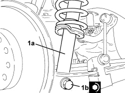
1. Connect the rear suspension shock absorbers (1a) to the rear suspension crossmember and tighten bolts (1b) to the specified torque.
| Component | Fastening | dia | Value (daNm) | Validity |
|---|---|---|---|---|
| Rear shock absorber | Bolt | M14 | (longitudinal arm side) 13.0 - 16.0 |
1. Position the rear brake caliper assemblies (1a) in their housings and secure them tightening the bolts (1b) to the recommended torque.
| Component | Fastening | dia | Value (daNm) | Validity |
|---|---|---|---|---|
| Rear brake caliper brackets | Bolt | M10 | (steering knuckle side) 5.4 - 6.0 |
2. Connect the handbrake control cable to the rear brake calipers.
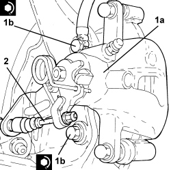
1. Refit the rear wheel rpm sensors (1a) in their seats on the stub axles and secure by tightening bolts (1b) to the specified torque.
| Component | Fastening | dia | Value (daNm) | Validity |
|---|---|---|---|---|
| Rear wheel rpm sensor | Bolt | M6 | (steering knuckle side) 0.7 - 1.1 |
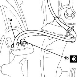
- Secure the handbrake control cables to the intermediate fastenings.
Op. 1076B30 FRONT EXHAUST SILENCER - R + R
Op. 1076B22 REAR EXHAUST SILENCERS (ONE) LH OR RH R R
Op. 4450B13 REAR WHEELS (TWO) - R.R
- Remove the vehicle from the lift.
Parts & tools for this job Staging For 2005 Alfa Romeo Brera
- TOOLCoil spring compressorSearch: coil spring compressor
- TOOLBall joint separatorSearch: ball joint separator
- PARTRear shock absorbersSearch: Alfa Romeo Brera 2005 rear shock absorbers
Links open Amazon search results in a new tab. As an Amazon Associate I earn from qualifying purchases.