
Front suspension frame - r+r
- Make
- Alfa Romeo
- Model
- Brera and Spider Factory Service Manual
- Year
- 2005–2010
- Section
- Front suspension › Front suspension frame - r+r
FRONT SUSPENSION FRAME - R+R
Removing
- Position the vehicle on a lift.
- Make sure that the ignition key is in the OFF position, then disconnect the battery terminal (-).
| Description | Connector | |
|---|---|---|
| Battery | See A001 BATTERY |
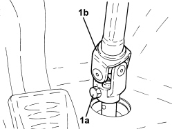
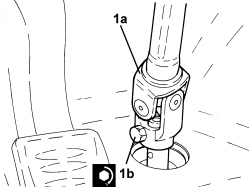
1. Undo the fixing bolt (1a) and disconnect the steering column (1b) from the steering box.
The bolt is the pre-treated type and it therefore cannot be reused when refitting.
Op. 4450B12 FRONT WHEELS (TWO) - R+R
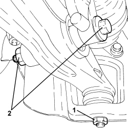
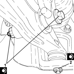
1. Undo the nuts securing the front suspension lower wishbones to the wheel steering knuckles.
2. Undo the bolts securing the lower forks connecting the front suspension shock absorbers to the lower wishbone, lower wishbone side.
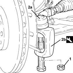
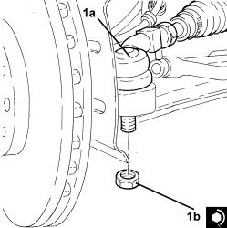
1. Undo the nuts fixing the steering rods to the steering knuckles.
2. Disconnect the steering rods (2a) from the front steering knuckle using the tool (2b).
| Tool | Description | Function | Validity |
|---|---|---|---|
| 1871000700 | Extractor | Extracting steering rod from steering knuckle |
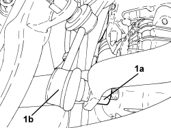
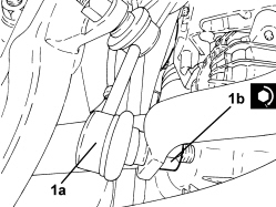
1. Undo the nuts (1a) and disconnect the front suspension anti-roll bar joints (1b).
1. Undo the lower bolts securing the reinforcements to the front suspension frame.
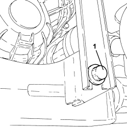
- Disconnect the front suspension lower wishbones from the wheel steering knuckle assemblies.
Op. 1076B72 INTERMEDIATE EXHAUST PIPE WITH HOSE SECTION - R+R
1. Undo the bolts fixing the power unit lower reaction rod, engine crankcase sump side.
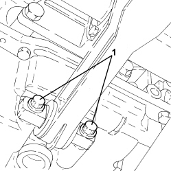
1. Undo the bolts fixing the power unit rear support flexible mounting, rigid support side.
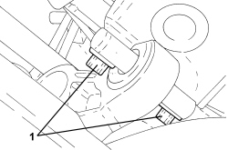
- Secure the engine cooling radiator to the headlamp beam.
- Draw off the power assisted steering fluid from the reservoir using a suitable syringe.
1. Undo the connector (1a) and disconnect the supply pipe from the pump to the power assisted steering box (1b), power assisted steering box side.
2. Undo the connector (2a) and disconnect the return pipe from the power steering box to the intermediate pipe (2b), power assisted steering box side.
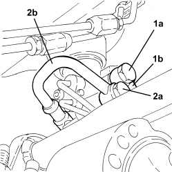
1. Undo the bolts fixing the front suspension frame to the bodyshell.
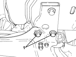
1. Position a hydraulic lift (1a) using tools (1b) to support the front suspension frame.
| Tool | Description | Function | Validity |
|---|---|---|---|
| 1870835001 | Hydraulic lift | Rear suspension crossmember support |
| Tool | Description | Function | Validity |
|---|---|---|---|
| 2000002300 | Support | Supporting front suspension frame |
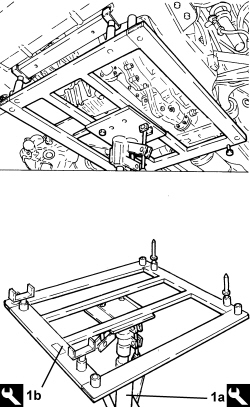
- If the above hydraulic lift is not available, use a general hydraulic lift plus the adaptor shown in the drawing, which must be made up by the workshop to allow the use of the above frames
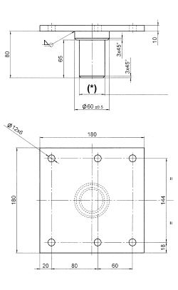
(*): Ensure the shank diameter fits the hydraulic lift used.
1. Unscrew the remaining bolts securing the rear suspension frame.
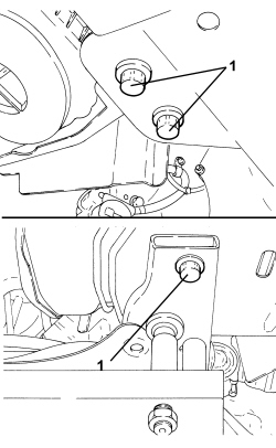
- Lower the hydraulic jack and remove the front suspension frame assembly.
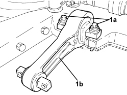
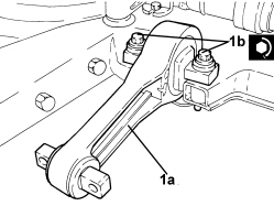
1. Working at the bench, undo the bolts (1a) and remove the power unit lower reaction rod (1b) from the front suspension frame.
Mark the position of the lower reaction rod for the power unit in relation to the front suspension frame.
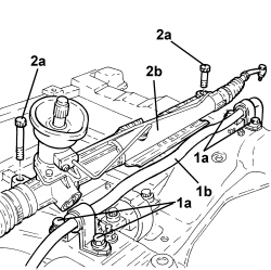
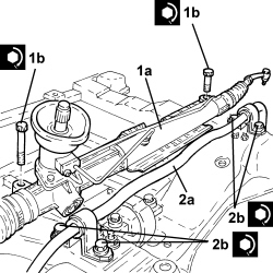
1. Undo the bolts (1a) and remove the anti-roll bar (1b) with joints from the front suspension frame.
2. Undo the bolts (2a) and remove the power steering box (2b) from the front suspension frame.
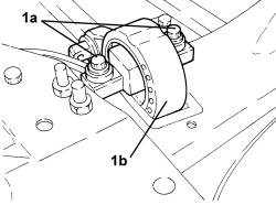
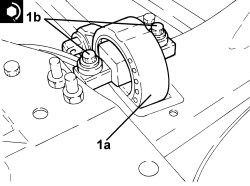
1. Undo the bolts (1a) and remove the flexible mounting for the power unit rear support (1b) from the front suspension frame.
Mark the position of the flexible mounting for the power unit rear support in relation to the front suspension frame.
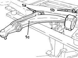
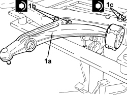
1. Undo bolts (1a), (1b) and remove the front suspension lower wishbones (1c) from the front suspension frame.
Mark the position of the front suspension lower wishbones in relation to the front suspension frame.
Refitting
1. Refit the front suspension wishbones (1a) in their seats on the front suspension frame and secure by tightening bolts (1b) to the specified torque and then by tightening bolts (1c) to the specified torque.
Ensure that they are in the position marked upon removal.
1. Place the power unit rear support flexible mounting block (1a) in its housing on the frame and secure it by tightening the bolts (1b) to the recommended torque.
Ensure that they are in the position marked upon removal.
| Component | Fastening | dia | Value (daNm) | Validity |
|---|---|---|---|---|
| Timing side flexible mounting to rigid support | Bolt (to be replaced) | M12 | 6.3 ÷ 7.7 + 90° |
1. Place the power steering box (1a) in its housing in the front suspension frame and secure it by tightening the bolts (1b) to the recommended torque.
| Component | Fastening | dia | Value (daNm) | Validity |
|---|---|---|---|---|
| Power assisted steering box | Bolt (to be replaced) | M12 | 11.3 ÷ 13.8 + 180° |
2. Place the anti-roll bar (2a) in its housing in the front suspension frame and secure it by tightening the bolts (2b) to the recommended torque.
| Component | Fastening | dia | Value (daNm) | Validity |
|---|---|---|---|---|
| Front suspension anti-roll bar | Front bolt | M8 | 2.2 ÷ 2.6 |
| Component | Fastening | dia | Value (daNm) | Validity |
|---|---|---|---|---|
| Front suspension anti-roll bar | Rear bolt (to be replaced) | M12 | 7.2 ÷ 8.8 + 90° |
1. Place the power unit lower reaction link (1a) in its housing on the front suspension frame and secure it by tightening the bolts (1b) to the recommended torque.
Ensure that they are in the position marked upon removal.
| Component | Fastening | dia | Value (daNm) | Validity |
|---|---|---|---|---|
| Engine side lower reaction rod to front suspension frame | Bolt (to be replaced) | M12 | 6.3 ÷ 7.7 + 60° |
- Refit the front suspension frame assembly using the mounting tools and hydraulic lift.
- Tighten the bolts securing the front suspension frame to the bodyshell to the recommended torque.
| Component | Fastening | dia | Value (daNm) | Validity |
|---|---|---|---|---|
| Front suspension frame | Front bolt (to be replaced) | M14 | 16.2 ÷ 19.8 + 90° |
| Component | Fastening | dia | Value (daNm) | Validity |
|---|---|---|---|---|
| Front suspension frame | Centre bolt (to be replaced) | M14 | 11.7 ÷ 14.3 + 90° |
| Component | Fastening | dia | Value (daNm) | Validity |
|---|---|---|---|---|
| Front suspension frame | Rear bolt (to be replaced) | M14 | 9.9 ÷ 12.1 + 90° |
- Remove the tool and the hydraulic jack used to support the front suspension frame.
| Tool | Description | Function | Validity |
|---|---|---|---|
| 2000002300 | Support | Supporting front suspension frame |
| Tool | Description | Function | Validity |
|---|---|---|---|
| 1870835001 | Hydraulic lift | Rear suspension crossmember support |
1. Connect the return pipe from the power assisted steering box to the intermediate pipe (1a), power assisted steering box side and tighten the connector (1b) to the recommended torque.
| Component | Fastening | dia | Value (daNm) | Validity |
|---|---|---|---|---|
| Return pipe from power assisted steering box | Connector | M12 | 2.7 ÷ 3.3 |
2. Connect the supply pipe from the pump to the power assisted steering box (2a), power assisted steering box side and tighten the connector (2b) to the recommended torque.
| Component | Fastening | dia | Value (daNm) | Validity |
|---|---|---|---|---|
| Supply pipe from pump to power assisted steering box - power steering box side | Connector | M14 | 3.6 ÷ 4.4 |
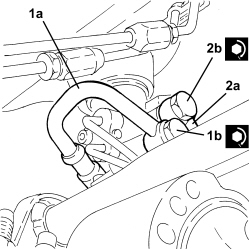
1. Tighten the bolts fixing the power unit rear support flexible mounting, rigid support side to the recommended torque.
| Component | Fastening | dia | Value (daNm) | Validity |
|---|---|---|---|---|
| Timing side flexible mounting to bodyshell | Bolt | M10 | 5.4 ÷ 6.6 |
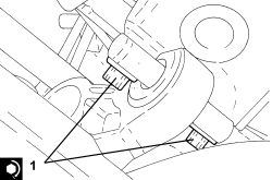
1. Tighten the bolts fixing the lower reaction rod for the power unit, engine crankcase sump side to the recommended torque.
| Component | Fastening | dia | Value (daNm) | Validity |
|---|---|---|---|---|
| Engine side lower reaction rod to engine | Bolt | M10 | 5.4 ÷ 6.6 |
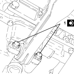
Op. 1076B72 INTERMEDIATE EXHAUST PIPE WITH HOSE SECTION - R+R
- Connect the front suspension lower wishbones to the wheel steering knuckle assemblies.
1. Tighten the lower bolts fixing the reinforcements to the front suspension frame to the recommended torque.
| Component | Fastening | dia | Value (daNm) | Validity |
|---|---|---|---|---|
| Underbody reinforcements | Bolt | M12 | 7.2 ÷ 8.8 |
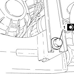
1. Connect joints (1a) to the front suspension stabiliser bar and secure by tightening nuts (1b) to the specified torque.
| Component | Fastening | dia | Value (daNm) | Validity |
|---|---|---|---|---|
| Front suspension anti-roll bar joint - anti-roll bar side | Nut | M12 | 9.0 ÷ 11.0 |
1. Connect the steering links (1a) to the front stub axles and tighten the nuts (1b) to the specified torque.
.
| Component | Fastening | dia | Value (daNm) | Validity |
|---|---|---|---|---|
| Steering rod to steering knuckle | Nut | M12 | 9.0 ÷ 11.0 |
1. Tighten the new bolts securing the lower forks connecting the front suspension shock absorbers to the lower wishbone, lower wishbone side, to the specified torque.
| Component | Fastening | dia | Value (daNm) | Validity |
|---|---|---|---|---|
| Lower fork connecting front suspension shock absorber to lower track control arm - lower track control arm side | Bolt (to be replaced) | M14 | 4.5 ÷ 5.5 + 90° |
2. tighten the nuts securing the front suspension lower wishbones to the wheel steering knuckles to the specified torque.
| Component | Fastening | dia | Value (daNm) | Validity |
|---|---|---|---|---|
| Front suspension lower track control arm - steering knuckle side | Nut | M14 | 8.1 ÷ 9.9 |
Op. 4450B12 FRONT WHEELS (TWO) - R+R
1. Connect steering column (1a) to the power steering box pinion and secure by tightening a new bolt (1b) to the specified torque.
| Component | Fastening | dia | Value (daNm) | Validity |
|---|---|---|---|---|
| Steering column | Bolt (to be replaced) | M8 | 2.3 ÷ 2.8 |
- Connect the negative battery terminal.
- Remove the vehicle from the lift.
Parts & tools for this job Staging For 2005 Alfa Romeo Brera
- TOOLCoil spring compressorSearch: coil spring compressor
- TOOLBall joint separatorSearch: ball joint separator
- PARTFront shock absorbersSearch: Alfa Romeo Brera 2005 front shock absorbers
Links open Amazon search results in a new tab. As an Amazon Associate I earn from qualifying purchases.