Workshop Manuals Factory service & repair Alfa Romeo
01 General information02 Specifications03 Manufacturing data and tolerances04 Tightening torques05 Fluids and lubricants06 Maintenance07 Diagnostic checks08 Engine09 Clutch10 Gearbox and differential11 Transmission (4x4)12 Axles and driveshafts13 Brakes14 Steering15 Suspension and wheels16 Heating, air conditioning and auxiliary units17 Electrical equipment18 Body fittings19 Body panels and frame20 Wiring diagrams and electrical functions21 Wiring harnesses22 Connectors and pin-outs23 Fault diagnosis24 Special tools
Alfa Romeo Brera and Spider Factory Service Manual (2005-2010)17 · Electrical equipment
17 · Electrical

Front buzzer operation check

Make
Alfa Romeo
Model
Brera and Spider Factory Service Manual
Year
2005–2010
Section
Special accessories › Front buzzer operation check
Electrical equipmentFront buzzer operation check

FRONT BUZZER OPERATION CHECK

Check 5580HE

STEPCHECK TO BE PERFORMEDRESOLUTION IF THE CHECK IS NOT OK
1

Check rear buzzer impedance

  • Connect the negative supply terminal for the Examiner to the vehicle earth
  • Switch on the Examiner and set it to ohmmeter mode and calibrate, bypassing the probes
  • Connect the leads (black and red probes) to the buzzer terminals without disconnecting it from the parking sensor control unit

The measurement should be about 51 Ohm which is the value for the buzzer impedance.

Replace buzzer
2

Check rear buzzer control line impedance

  • Disconnect the buzzer connector
  • Connect the ohmmeter to the connector terminals and measure a value of 230 Kohm which should be the system impedance
  • Renew the wiring continuity between the parking control unit and the buzzer see wiring diagram

See E3090 PARKING SENSOR

  • Replace the parking sensor control unit

Op. 5580H10 PARKING OBSTACLE DETECTION DEVICE ELECTRONIC CONTROL UNIT - R.R.

3

Check the buzzer positive power supply

  • Place the key in the ON position

Press the parking sensor disablement button and ensure the led on the button comes on to indicate enablement.

With the Examiner in voltmeter mode.

  • Connect between pin of parking sensor control unit connector LA and earth and ensure a voltage of 12 Volts is present
  • Restore wiring continuity between the parking control unit and the buzzer

See E3090 PARKING SENSOR

  • Replace the parking sensor control unit

Op. 5580H10 PARKING OBSTACLE DETECTION DEVICE ELECTRONIC CONTROL UNIT - R.R.

4

Check the buzzer signal

  • Place the key in the ON position

Press the parking sensor disablement button and ensure the led on the button comes on to indicate enablement.

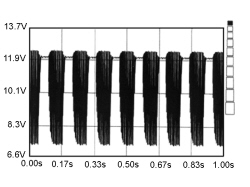
  • With the Examiner in voltmeter mode, select an full scale deflection of 20 Volt and time base of 1 second
  • Connect the red voltmeter probe to pin 2 of connector LA of the parking control unit and the black probe to earth

Get close to the rear sensors with the device working, check for the presence of the electrical signal.

Press the START button on the Examiner.

The image that appears should be similar to the one below

  • Renew the wiring continuity between the parking control unit and the buzzer see wiring diagram

See E3090 PARKING SENSOR

  • Replace the parking sensor control unit

Op. 5580H10 PARKING OBSTACLE DETECTION DEVICE ELECTRONIC CONTROL UNIT - R.R.

5

Check buzzer operation

Check that the buzzer is working properly in the presence of the buzzer activation signal and the positive power supply

Replace buzzer
FRONT BUZZER OPERATION CHECK

Parts & tools for this job Staging For 2005 Alfa Romeo Brera

Links open Amazon search results in a new tab. As an Amazon Associate I earn from qualifying purchases.