
Clock spring
- Make
- Alfa Romeo
- Model
- 147 Factory Service Manual
- Year
- 2000–2002
- Section
- Warning and manoeuvring indicators › Clock spring
CLOCK SPRING
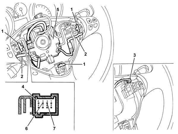
- 1 Spring
- 2 Printed circuit
- 3 Horn connection for versions without radio/Selespeed controls on the steering wheel
- 4 Horn connection for versions with radio/Selespeed contols on the steering wheel
- 5 Junction unit
- 6 Horn positive pin signal
- 7 Horn negative pin signal
The pressure exerted on the centre of the steering wheel causes the compressino of one of the three springs, near the bolts fixing the Air Bag module (see Subassembly 5580C) which closes the circuit to earth.
View of horn control circuit
The three springs form part of a printed circuit, in the partition housing the Air Bag module (see Subassembly 5580C) which ends with a two-way connection.
For versions without radio controls on the steering wheel, the connection to the electrical system is via a bridge (which connector) which comes out of the clock spring.
For versions with radio (see Subassembly 5570T) and Selespeed (see Subassembly 2127A) controls on the steering wheel, the bridge connecting the horns comes out of the junction unit, at the bottom of the housing. The casing is, in turn, connected, via
an eight-way connector, to the bridge which comes out of the clock spring.
The connection to the system, via the clock spring, allows the rotation of the steering wheel, ensuring the correct transmission of the various signals, without the aid of sliding contacts.
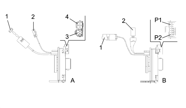
- A - Clock spring for versions without radio/Selespeed controls on the steering wheel
- B - Clock spring for versions with radio/Selespeed controls on the steering wheel
- 1 Connector connecting Air Bag module (steering wheel side)
- 2 Connector connecting horns (steering wheel side)
- 3 Connection point for connecting Air Bag module
- 4 Connection point for connecting horns (steering column switch unit side)
- P1 - Horn positive signal pin
- P2 - Horn negative signal pin
On versions without radio controls on the steering, on the side the clock spring is fixed to the steering column switch unit it has two connection points, one for the horn signal and one for the connection to the Air Bag module whilst on versions with
radio/telephone and Selespeed controls on the steering wheel the connection is achieved via a single twelve-way connector.
View of connection points to electrical system:
The clock spring signal goes to the junction unit B1 and is sent to the horn.
To consult the functional diagram, see chart E 3010 HORNS
The connecting cables should be fitted in the appropriate housing, at the base of the housing, to prevent possible interference with the Air Bag module.
Parts & tools for this job Staging For 2000 Alfa Romeo 147
- TOOLCoil spring compressorSearch: coil spring compressor
- TOOLBall joint separatorSearch: ball joint separator
- PARTShock absorbersSearch: Alfa Romeo 147 2000 shock absorbers
Links open Amazon search results in a new tab. As an Amazon Associate I earn from qualifying purchases.