
Pin out
- Make
- Alfa Romeo
- Model
- 147 Factory Service Manual
- Year
- 2000–2002
- Section
- Instruments › Pin out
Electrical equipmentPin out
PIN OUT
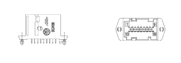
- 1 INT. +15 from fuse F37
- 2 +30 from fuse F53
- 3 B-CAN A
- 4 B-CAN B
- 5 Headlamp aglinment actuators signal reference
- 6 Dipped headlamps positive from fuse F13 for headlamp alignment
- 7 Earth
- 8 Negative signal from trip computer button on steering column switch unit
- 9 Signal from controls on PCS (left panel) (zero km, mode -)
- 10 Negative signal i.e. warning light failure/EOBD from N.C.M.
- 11 Signal from P.C.S. (headlamps up, headlamps down)
- 12 Inertia switch intervention signal FPS (NA)
- 13 C.A.B. failure warning light negative signal (AIR BAG)
- 14 Passenger Air Bag disabled warning light negative signal
- 15 Driver's seat belt not fastened negative signal
- 16 Signal from controls at P.C.S. (MODE MODE +)
- 17 Engine oil level sensor supply (TDS only)
- 18 Signal from engine oil lever sensor (TDS only)
The diagram below illustrates the PIN OUT.
Parts & tools for this job Staging For 2000 Alfa Romeo 147
- TOOLDigital multimeterSearch: automotive digital multimeter
- PARTAssorted fuse kitSearch: car fuse assortment kit
- TOOLWire crimper and connector kitSearch: wire crimper connector kit
Links open Amazon search results in a new tab. As an Amazon Associate I earn from qualifying purchases.