
Introduction
- Make
- Alfa Romeo
- Model
- 147 Factory Service Manual
- Year
- 2000–2002
- Section
- Traction control › Introduction
Introduction
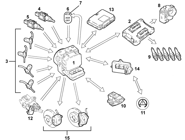
The VDC system continuously detects loss of longitudinal and transverse wheel grip under all driving conditions, from braking to acceleration, to ensure vehicle directionality and stability.
The VDC system is managed by a Bosch 5.7 ABS ECU integral with a special hydraulic control unit that makes it possible for the brake system to be operated independently of the driver.
The control unit processes the following signals:
steering angle/steering wheel rotation speed sensor
side acceleration sensor and yaw sensor,
motorised throttle position
wheel rpm sensors
hydraulic system pressure sensor
and uses special algorhythms in the software to obtain the values for dynamic control:
longitudinal and transverse slip between wheels and road surface
axle drift.
The system calculate actual vehicle dynamics from these values; and identifies all critical conditions due to environmental factors (e.g. surface with poor grip) or any mistakes made by the driver (e.g. panic situations) to restore the car to
efficient handling conditions by adjusting the brakes and drive torque.
The system interfaces with:
NCM for drive torque modulation,
NCR (robotised gearbox node) for gear shift management
NBC (body computer node) to transmit vehicle speed values and control warning lights.
Information is exchanged between these components by means of the C-CAN and B-CAN lines.
System diagnosis is carried out via a dedicated line (K line).
The system is linked to a power unit with a special brake pump; the pipes between brake pump and ABS control unit are also fitted with a Titaflex insert because the pipe diameter is bigger (6 mm) than normal pipes (4 mm). this is to prevent negative
effects on VDC operation at low brake fluid temperatures.
The VDC comes on automatically when the vehicle is started up and cannot be switched off by the driver. the button on the central console turns off only the ASR function and only in recommended circumstances (see ASR system)
INPUT SIGNALS
Wheel speed sensor (from direct line) 3
Normally open brake pedal sensor (from direct line) 4
normally closed brake pedal sensor (from direct line) 5
ASR button off (from direct line) 6
Engine control unit 2
Throttle angle position (from C-CAN line)
Body computer 14
Handbrake lever position (from C-CAN line)
Warning light status indicator (from C-CAN line)
Yaw sensor (rotation around vehicle vertical axis (from direct line) 10
Lateral acceleration sensor (from direct line) 10
Steering wheel steering angle/rotation sensor ((from C-CAN line) 12
Robotised gearbox control unit (speed engaged status) (from C-CAN line) 13
Hydraulic system pressure sensor(from direct line) 1
OUTPUT SIGNALS
Brake pressure modulation command 15
Ignition advance reduction command (from C-CAN line) 9
Engine power management command (from C-CAN line) 8
Gear change inhibition (from C-CAN line) 13
Wheel speed signal for speedometer and mileometer (from C-CAN line) 14.
VSO (vehicle speed) signal 14
VDC warning light control on panel (from C-CAN line) 11
ASR led off 7
Parts & tools for this job Staging For 2000 Alfa Romeo 147
- TOOLOBD2 scanner with ABSSearch: OBD2 scanner ABS SRS
- TOOLDigital multimeterSearch: automotive digital multimeter
Links open Amazon search results in a new tab. As an Amazon Associate I earn from qualifying purchases.