
POWER STEERING BOX
- Make
- Land Rover
- Model
- Defender 300Tdi Defender
- Section
- POWER STEERING BOX
57
STEERING
4
REPAIR
POWER STEERING BOX
Service repair no - 57.10.01
NOTE: A chassis undertray may be fitted
on some vehicle derivatives to conform to
legal requirements. When under chassis
remove and refit procedures are required, it may
be necessary to remove the undertray
See
CHASSIS AND BODY, Repair, Front undertray .
General precautions
Whenever any part of system, is removed or
disconnected, utmost cleanliness must be
observed.
Disconnected ports and hoses must be
plugged to prevent ingress of dirt. If metal
sediment is found in system, establish cause,
rectify and flush system.
Do not start engine until reservoir is full as
pump will be damaged.
Metric pipe fittings are used with ’O’ ring pipe
ends on fittings to steering box.
Follow normal ’O’ ring replacement procedure
whenever pipes are disconnected.
Ensure compatible metric components when
fitting replacement pipes.
CAUTION: After refitting steering linkage
parts follow correct procedure to ensure
that road wheels, steering box and
steering wheel are correctly positioned relative to
each other when in straight ahead condition.
NOTE: When drag link is disconnected
from steering box, travel available at
steering wheel to each full lock is not
equal.
Remove
1. Site vehicle on level surface.
2. Apply park brake, chock rear wheels, raise
vehicle and locate axle stands. Alternatively,
raise vehicle on a hoist.
3. Remove road wheel.
4. Remove panhard rod
See FRONT
SUSPENSION, Repair, Panhard rod .
5. Disconnect steering damper from drag link.
6. Disconnect drag link from drop arm, see J6305
on opposite page, using a suitable extractor.
7. Slacken, but do not remove nut securing tie bar
to mounting arm.
8. Remove 2 bolts securing tie bar to steering box
and move aside.
9. Remove filler cap from power steering fluid
reservoir.
10. Position suitable container under steering box.
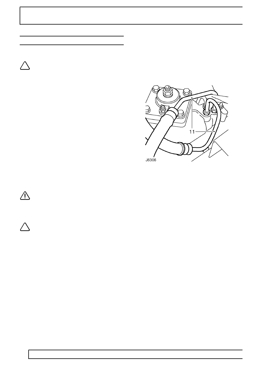
11. Disconnect feed and return pipes from steering
box and drain fluid.
12. Plug open pipes and steering box ports to
prevent ingress of dirt. Refit fluid reservoir filler
cap.
13. Centralise steering
See Centralise steering
box .
14. Remove pinch bolt securing lower shaft
universal joint to power steering box.
15. Remove 4 bolts and 2 tab washers securing
steering box to chassis side member.
16. Withdraw steering box.
17. Clean all mounting faces, unions etc. prior to
refitting.
Refit
18. Position steering box to chassis side member,
ensuring locating peg is engaged. Fit tab
washers and tighten bolts to
81 Nm (60 lbf/ft).
19. Fit pinch bolt and nut securing universal joint to
power steering box spline. Tighten to
25 Nm (18
lbf/ft).
20. Secure tie bar to mounting arm and steering box.
Tighten fixings to
81 Nm (60 lbf/ft), starting with
tie bar to mounting nut, then loosen fixings by
one complete turn.
21. Check steering box and adjust if necessary
See
Adjustment, Power steering box - adjust .
22. Refit drag link to drop arm and tighten nut to
40
Nm (30 lbf/ft). Fit new split pin to retaining nut.
Parts & tools for this job Staging For Land Rover Defender
- TOOLTie rod end toolSearch: tie rod end puller
- TOOLBall joint separatorSearch: ball joint separator
- FLUIDPower steering fluidSearch: Land Rover power steering fluid
Links open Amazon search results in a new tab. As an Amazon Associate I earn from qualifying purchases.