
PROPELLER SHAFT
- Make
- Land Rover
- Model
- Defender 300Tdi Defender
- Section
- PROPELLER SHAFT
PROPELLER SHAFTS
1
DESCRIPTION AND OPERATION
PROPELLER SHAFT
Description
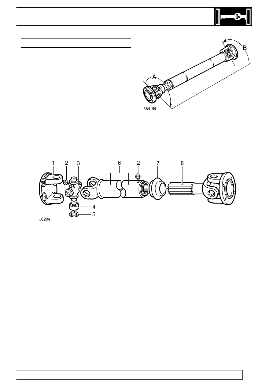
The front and rear propeller shafts have non-constant
velocity type universal joints, with needle roller
bearings. The bearing cups are pre-packed with
lubricant on assembly and a grease nipple is fitted for
servicing as specified, in maintenance section.
Both shafts have Rilsan coated sliding splines to
accommodate the variation in distance between the
axles and transmission. The splines are pre-packed
with lubricant and protected by a rubber gaiter. A
grease nipple is also fitted for servicing requirements.
The front shaft which is shorter than the rear is
’phased’, with the joints at each end, A and B
mis-aligned as shown.
The phasing is necessary on the front shaft only to
allow for greater variation in angular changes.
Propeller shaft
1. Flanged yoke
2. Grease nipple
3. Journal spider
4. Needle roller bearing
5. Circlip
6. Splined shaft
7. Rubber gaiter (dust cap)
8. Splined shaft
Parts & tools for this job Staging For Land Rover Defender
- TOOLTorque wrenchSearch: 3/8 inch torque wrench
- TOOLSocket setSearch: socket set metric
- BOOKHaynes manualSearch: Haynes manual Land Rover Defender
Links open Amazon search results in a new tab. As an Amazon Associate I earn from qualifying purchases.