
INJECTION PUMP TIMING - CHECK AND ADJUST
- Make
- Land Rover
- Model
- Defender 300Tdi Defender
- Section
- INJECTION PUMP TIMING - CHECK AND ADJUST
FUEL SYSTEM
3
ADJUSTMENT
INJECTION PUMP TIMING - CHECK AND ADJUST
Service repair no - 19.30.01
1. Viewing the valve mechanism through oil filler
aperture, turn crankshaft clockwise until inlet
valve of No.1 cylinder has just closed. No.1
cylinder is now just before TDC.
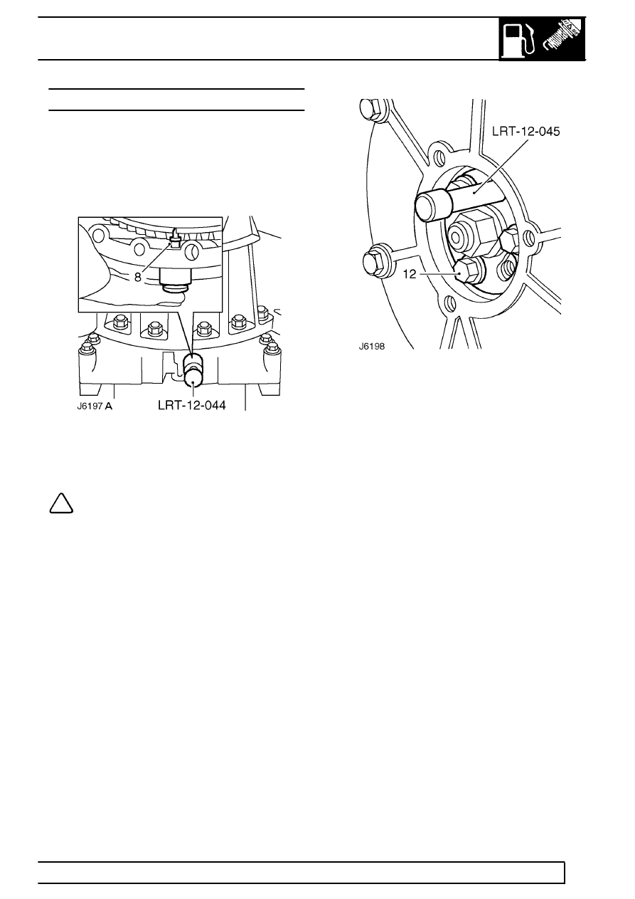
2. Remove blanking plug from flywheel housing
and insert timing tool LRT-12-044, locating
centre pin on flywheel.
NOTE: A chassis undertray may be fitted
on some vehicle derivatives to conform to
legal requirements. When under chassis
adjustments or remove and refit procedures are
required, it may be necessary to remove the
undertray and/or integral access panels.
See
CHASSIS AND BODY, Repair, Front undertray or
See CHASSIS AND BODY, Repair, Rear undertray
3. Cearfully rotate crankshaft clockwise until centre
pin engages timing slot in flywheel.
4. Remove injection pump access plate, complete
with gasket, from front cover plate.
5. Fit locking pin LRT-12-045/2 to injection pump
gear. If difficulty is experienced in inserting pin,
adjustments will be needed to correctly set
injection pump timing as follows:
6. Support injection pump retaining nut to prevent
strain on timing belt.
7. Slacken the 3 keeper plate retaining bolts.
8. Carefully turn fixing nut and keeper plate until
locking pin can be inserted, without restriction,
into injection pump gear.
9. Tighten keeper plate bolts to
25 Nm (18 lbf/ft)
and remove locking pin.
10. Refit injection pump access plate plate and
gasket.
11. Remove flywheel timing tool and refit blanking
plug.
12. Run engine until normal operating temperature is
reached and check that idle speed adjustment,
See low and high idle speed adjustment and
throttle cable adjustment
See Throttle cable
are correct.
Parts & tools for this job Staging For Land Rover Defender
- PARTGlow plugsSearch: Land Rover Defender glow plugs
- TOOLGlow plug socketSearch: glow plug socket
- TOOLDiesel compression testerSearch: diesel compression tester
Links open Amazon search results in a new tab. As an Amazon Associate I earn from qualifying purchases.