
DISTRIBUTOR - V8i (page 2 of 2)
- Make
- Land Rover
- Model
- Range Rover Classic
- Section
- REPAIR
ELECTRICAL
5
REPAIR
Refit
NOTE: If a new distributor is being fitted,
mark body in same relative position as
distributor removed.
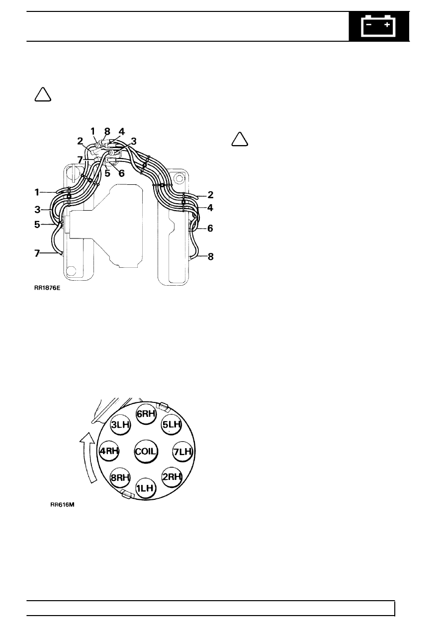
8. Leads for distributor cap should be connected as
illustrated.
Figures 1 to 8 inclusive indicate plug lead
numbers.
RH-Right hand side of engine, when viewed
from rear.
LH-Left hand side of engine, when viewed from
rear.
9. If engine has not been turned while distributor
has been removed, carry out instructions 10. to
17. Alternatively proceed to instruction 18.
10. Fit new ’O’ ring seal to distributor housing.
11. Turn distributor drive until centre line of rotor arm
is 30˚ anti-clockwise from mark made on top
edge of distributor body.
12. Position distributor to engine, connect multiplug
to amplifier; fit distributor in accordance with
alignment markings.
NOTE: It may be necessary to align oil
pump drive shaft to enable distributor
drive shaft to engage in slot.
13. Fit clamp and bolt. Secure distributor in exact
original position.
14. Connect vacuum hose to distributor and low
tension lead to coil.
15. Fit distributor cap.
16. Reconnect battery.
17. Using suitable electronic equipment, set ignition
timing.
See Adjustment, Ignition Timing
18. If engine has been turned with distributor
removed, carry out instructions 19. to 29.
19. Set engine-No. 1 piston to static ignition timing
figure.
If engine is 3.9 V8i.
See ENGINE TUNING
DATA, Information, ENGINE 3.9 V8i.
If engine is 4.2 V8i.
See ENGINE TUNING
DATA, Information, ENGINE 4.2 V8i.
20. Turn distributor drive until rotor arm is
approximately 30˚ anti-clockwise from number
one sparking plug lead position on cap.
21. Fit distributor to engine.
22. Check that centre line of rotor arm is now in line
with number one sparking plug lead on cap.
Reposition distributor if necessary.
23. If distributor does not seat correctly in front
cover, oil pump drive is not engaged. Engage by
lightly pressing down distributor while turning
engine.
24. Fit clamp and bolt, do not tighten.
25. Set ignition timing statically.
If engine is 3.9 V8i.
See ENGINE TUNING
DATA, Information, ENGINE 3.9 V8i.
If engine is 4.2 V8i.
See ENGINE TUNING
DATA, Information, ENGINE 4.2 V8i.
26. Connect vacuum hose to distributor.
27. Fit distributor cap.
28. Reconnect battery negative lead.
29. Using suitable electronic equipment set the
ignition timing.
See Adjustment, Ignition
Timing
Parts & tools for this job Staging For Land Rover Range Rover
- PARTSpark plugsSearch: Land Rover Range Rover spark plugs
- TOOLSpark plug socketSearch: spark plug socket
- TOOLSpark plug gap toolSearch: spark plug gap tool
Links open Amazon search results in a new tab. As an Amazon Associate I earn from qualifying purchases.