
ROTARY COUPLER
- Make
- Land Rover
- Model
- Range Rover Classic
- Section
- REPAIR › ROTARY COUPLER
CRUISE CONTROL - V8i
3
REPAIR
ROTARY COUPLER
Service repair no - 19.75.54
The rotary coupler is located behind the steering
wheel. Access is gained by removing the steering
wheel and steering column shroud.
NOTE: On vehicles fitted with airbags.
See
SUPPLEMENTARY RESTRAINT SYSTEM,
Repair, Rotary Coupler
Remove
1. Disconnect battery negative lead.
2. Remove steering wheel.
See STEERING,
Repair, Steering Wheel
3. Release 2 turnbuckles securing lower dash
closing panel and lower.
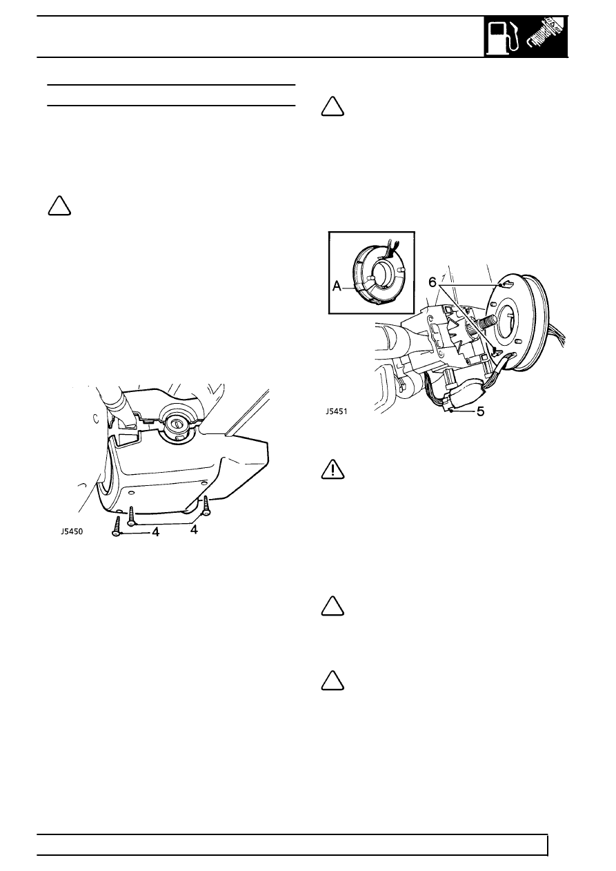
4. Remove 3 screws securing lower half of shroud
to steering column.
5. Disconnect rotary coupler multiplug from
steering column harness.
NOTE: If rotary coupler is to be re-used a
piece of adhesive tape should be placed
around the moulding in position A to
prevent rotation. Failure to do this may result in
damage to the wires inside the coupler.
6. Release clips securing rotary coupler to column
stalk assembly.
7. Remove rotary coupler from column stalk
assembly.
CAUTION: Ensure front wheels are in the
straight ahead position before removal
and refitting. Store in a plastic bag. DO
NOT rotate mechanism whilst removed.
Refit
8. Reverse removal procedure. Ensuring that the
column harnesses are not trapped by the
column shroud.
NOTE: If original rotary coupler is to be
fitted and there is evidence of tampering, it
is imperative that the coupler is
centralised.
See SUPPLEMENTARY RESTRAINT
SYSTEM, Repair, Rotary Coupler Centralise
NOTE: If a new rotary coupler is to be
fitted and the sealing tape is broken it
MUST NOT be used. Ensure rotary coupler
lugs are correctly engaged in the rear of the
steering wheel.
Parts & tools for this job Staging For Land Rover Range Rover
- PARTFuel filterSearch: Land Rover Range Rover fuel filter
- TOOLFuel pressure test kitSearch: fuel pressure test kit
- TOOLFuel line disconnect toolSearch: fuel line disconnect tool
Links open Amazon search results in a new tab. As an Amazon Associate I earn from qualifying purchases.